
Cylinder head of an internal combustion engine

a technology of internal combustion engine and cylinder head, which is applied in the direction of engine cooling apparatus, cylinders, liquid cooling, etc., can solve the problem of insufficient cooling of the thermally highly loaded areas around the outlet orifices close to the middle of the cylinder, and achieve good heat dissipation on the inlet side

Active Publication Date: 2014-03-04
AVL LIST GMBH
View PDF15 Cites 4 Cited by
  • Summary
  • Abstract
  • Description
  • Claims
  • Application Information

AI Technical Summary

Benefits of technology

The invention is designed to improve cooling in the cylinder head of an engine and avoid the need for excessive coolant quantities. It achieves this by using a first coolant passage and a second coolant jacket that are separated from one another. The first coolant passage cools the inlet side of the cylinder head while the second coolant jacket cools the outlet side. This ensures that the two sides can be cooled independently, with optimal dissipation of heat. Overall, the invention allows for a stronger and more compact cylinder head design.

Problems solved by technology

It is disadvantageous that thermally highly loaded areas around the outlet orifices close to the middle of the cylinder are cooled only insufficiently.

Method used


Image

  • Cylinder head of an internal combustion engine
  • Cylinder head of an internal combustion engine
  • Cylinder head of an internal combustion engine

Examples


Embodiment Construction

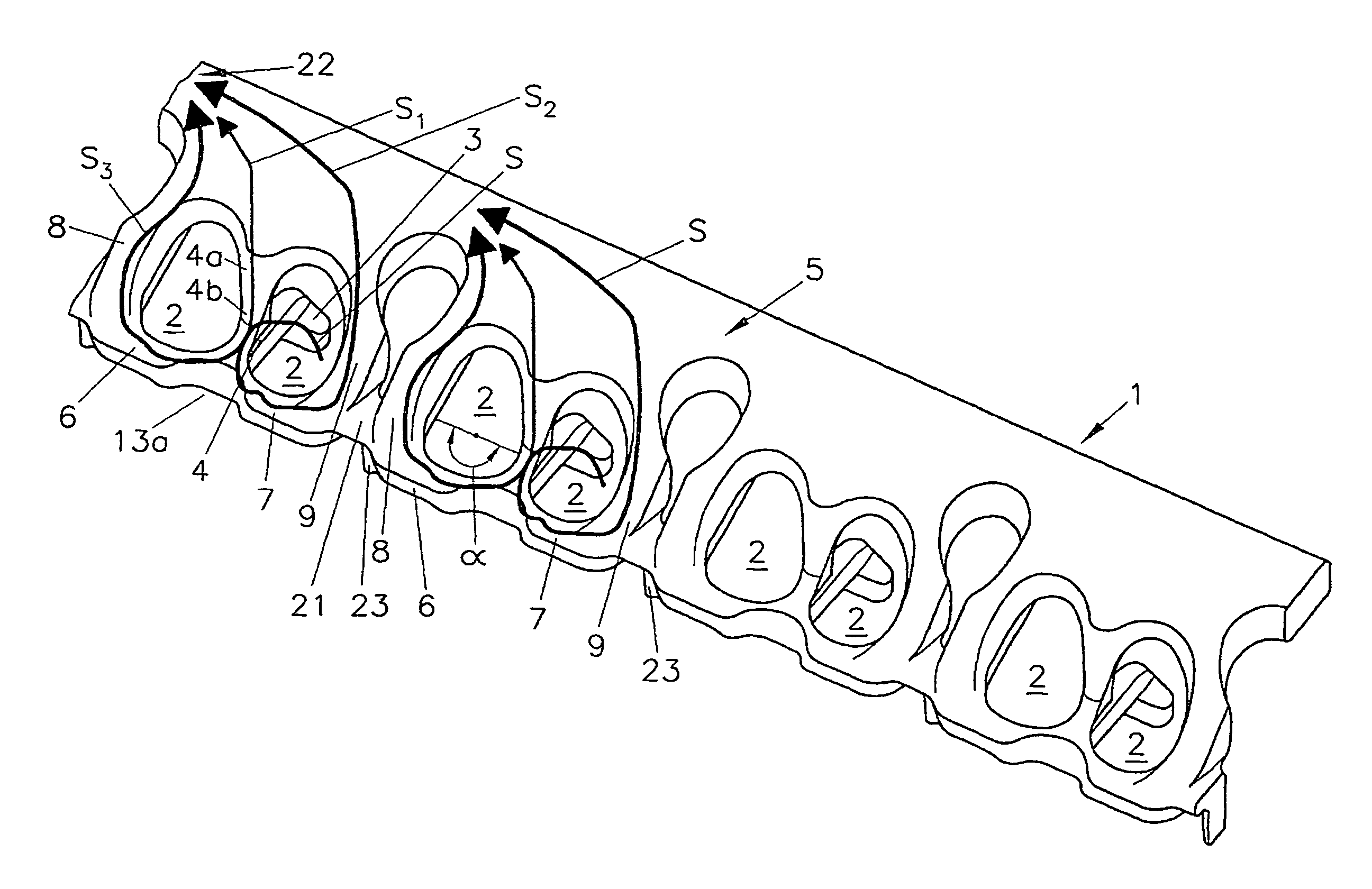
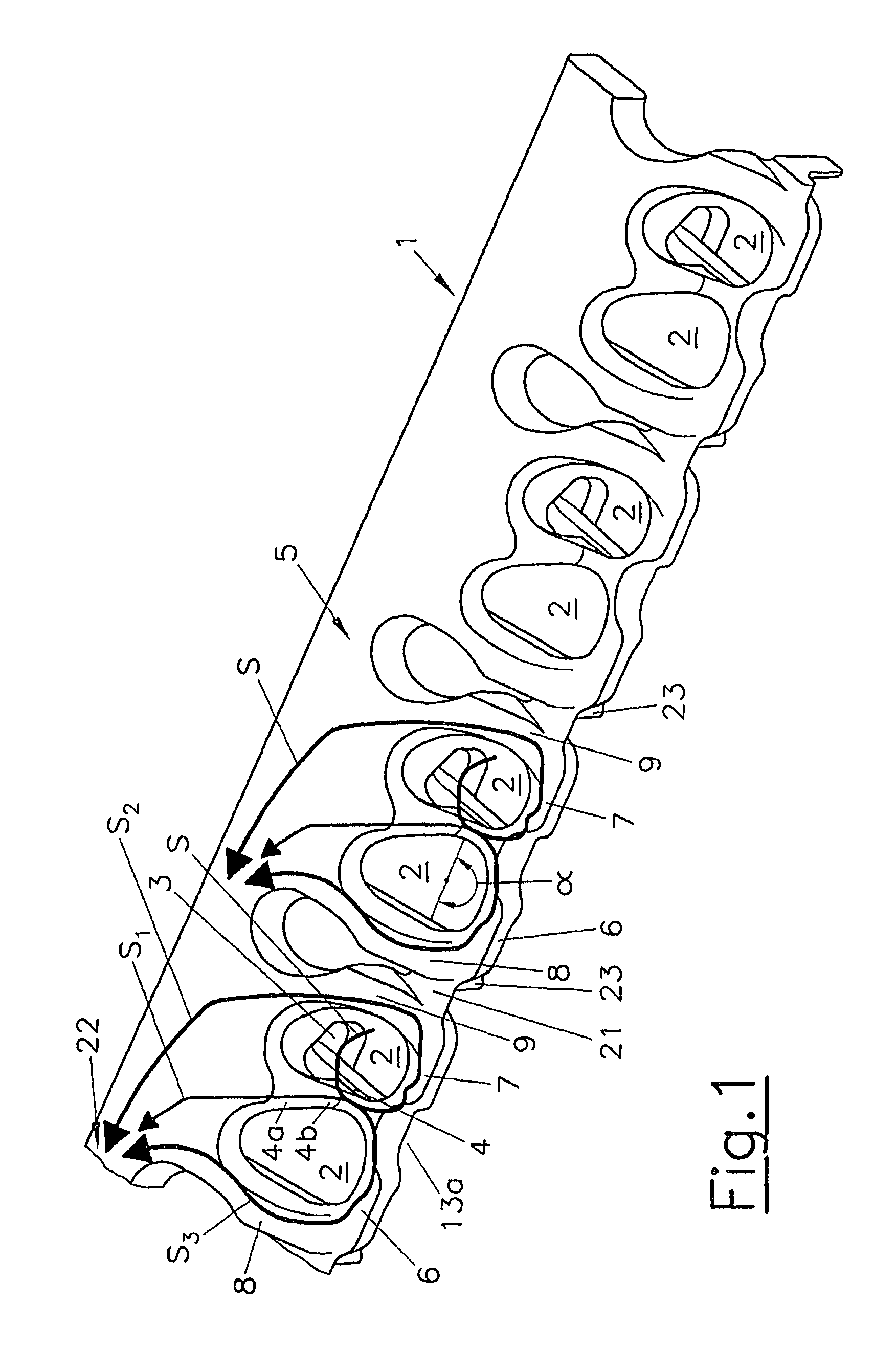
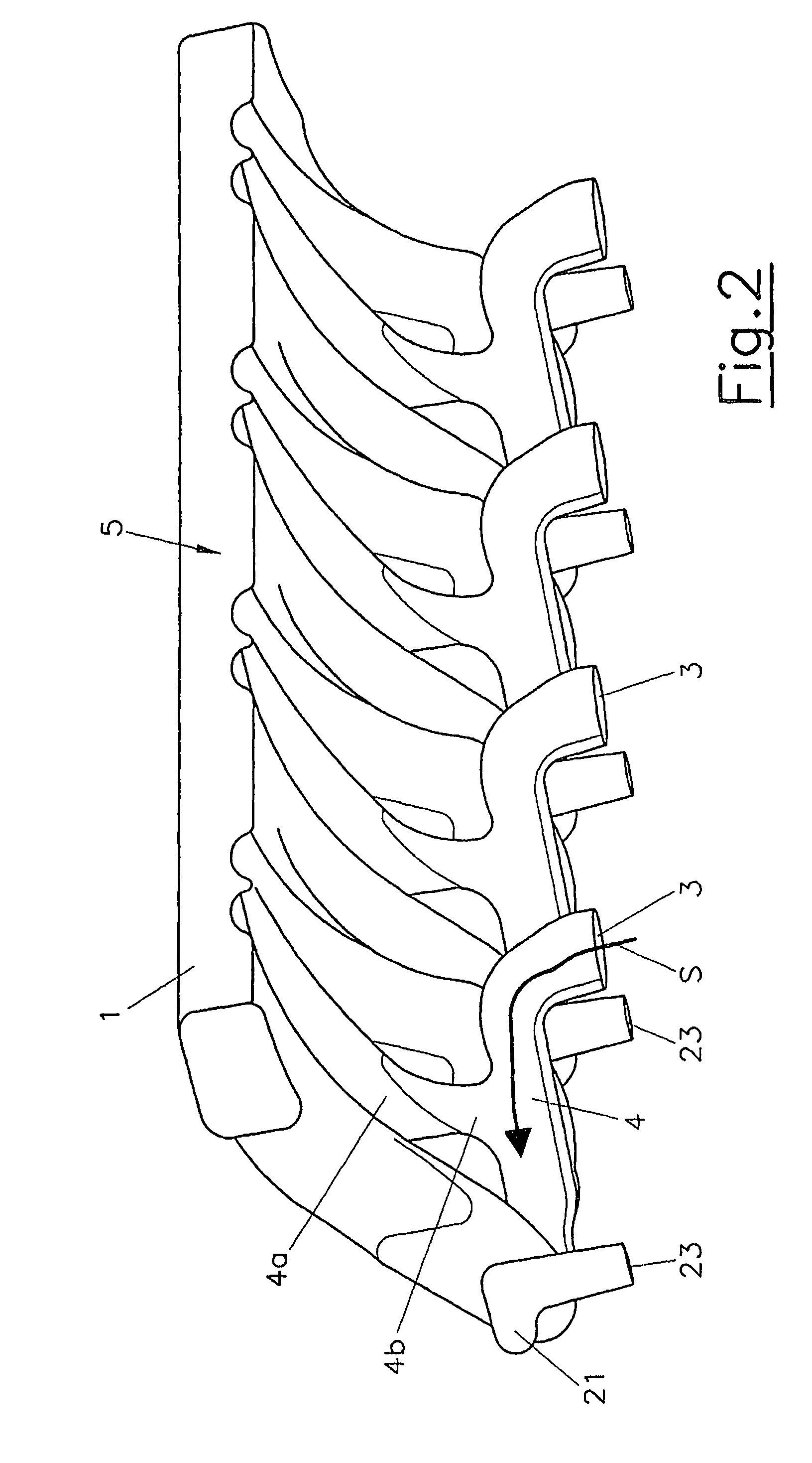
[0035]The cylinder head 10 as shown in FIG. 8 and FIG. 9 comprises a first coolant jacket 1 which is arranged completely on the outlet side 11 of the cylinder head 10. The outlet side 11 and the inlet side 12 of the cylinder head 10 are disposed on different sides of a longitudinal engine plane 14 extending through the cylinder axes 13. The first coolant jacket 1 is explicitly shown in FIG. 1 to FIG. 7. It comprises a first coolant collection channel 5 which extends in the longitudinal direction of the cylinder head 10 above the outlet channels, which is the side of the outlet channels facing away from the cylinder head gasket plane 15. A first transfer opening 3 is arranged per cylinder in the cylinder head gasket plane 15 in the region of a first transverse engine plane 16 extending through the cylinder axis 13 between two respective outlet channels 17. A first transverse cooling passage 4 which is arranged in the first transverse engine plane 16 extends from each transfer opening...


PUM


Abstract

A cylinder head of an internal combustion engine with several cylinders includes an inlet side and an outlet side with at least two outlet channels per cylinder, wherein a first coolant jacket is arranged in the cylinder head, the first coolant jacket including a first coolant collection channel which extends along the cylinder head on the outlet side over the outlet channels. The first coolant collection channel is connected to cooling chambers at least partially surrounding the outlet channels, the cooling chambers being in a fluidic connection with at least one transfer opening in a cylinder head gasket plane, wherein one first transfer opening per cylinder is arranged in a first transverse engine plane containing a cylinder axis, and wherein a first transverse cooling passage extends from each first transfer opening in the first transverse engine plane between two respective outlet channels, the first transverse cooling passage splitting into two cooling sub-passages in the area of the cylinder axis. Each cooling sub-passage respectively surrounds an outlet channel in the area of a respective outlet opening over an angle (α) of approximately 180° and each cooling sub-passage is connected to the coolant collection channel by means of a second transverse cooling passage, wherein each second transverse cooling passage is arranged in the area of a second transverse engine plane extending through at least one cylinder head bolt bore.

Description

BACKGROUND OF THE INVENTION[0001]1. Field of the Invention[0002]The invention relates to a cylinder head of an internal combustion engine having several cylinders, comprising an inlet side and an outlet side with at least two outlet channels per cylinder, wherein a first coolant jacket is arranged in the cylinder head, said first coolant jacket comprising a first coolant collection channel which extends along the cylinder head on the outlet side over the outlet channels, wherein the first coolant collection channel is connected to cooling chambers at least partially surrounding the outlet channels, said cooling chambers being in a fluidic connection with at least one transfer opening in a cylinder head gasket plane, wherein one first transfer opening per cylinder is arranged in a first transverse engine plane containing a cylinder axis, and wherein a first transverse cooling passage extends from each first transfer opening in the first transverse engine plane between two respective ...

Claims


Application Information

Patent Timeline
IPC IPC(8): F02F1/36
CPCF01P3/14F02F1/40
Inventor KNOLLMAYR, CHRISTOF
Owner AVL LIST GMBH
Learn More