

Electromagnetic fuel injection valve
a fuel injection valve and electromagnet technology, applied in the direction of valve operating means/release devices, machines/engines, mechanical equipment, etc., can solve the problems of increasing the adhering force of the valve body, adhesive wear in the seat portion, and the performance of the electromagnetic fuel injection valve is significantly degraded, so as to prevent the adhesive wear from occurring
Active Publication Date: 2014-03-04
HITACHI ASTEMO LTD
View PDF14 Cites 1 Cited by
- Summary
- Abstract
- Description
- Claims
- Application Information
AI Technical Summary
Benefits of technology
The present invention provides an electromagnetic fuel injection valve that uses a valve body and valve seat member made of martensitic stainless steel to prevent adhesive wear when injecting alcohol fuel. By using different stainless steels for the valve body and valve seat member, the hardness of the valve body is made higher than that of the valve seat member to reduce adhesive wear. The valve body and valve seat member can also be passivated to enhance their anti-corrosive performance and improve the merchantability of the valve. The stopper member is made of a different stainless steel that has lower hardness than the valve body to prevent adhesive wear in the abutment portion. These technical features can stabilize the fuel injection characteristic and suppress cost increase.
Problems solved by technology
However, when used to inject alcohol fuel, this electromagnetic fuel injection valve proves to have a significantly degraded performance.
When the electromagnetic fuel injection valve is used to inject alcohol fuel, adhesive wear occurs in a seat portion where the valve body is seated on the valve seat member under the influence of formic acid and acetic acid existing in the alcohol fuel.
Otherwise, the area of a seat portion between the valve body and the valve seat increases, and this increases an adhering force of the valve body.
As a result, the responsiveness of the valve body for its opening operation decreases, and this accordingly decreases the amount of injected fuel.
However, such a material is so expensive that the costs for the electromagnetic fuel injection valve considerably increases.
For this reason, the choice of such a material is not favorable.
Method used
View moreImage
Smart ImageViewing Examples

Examples
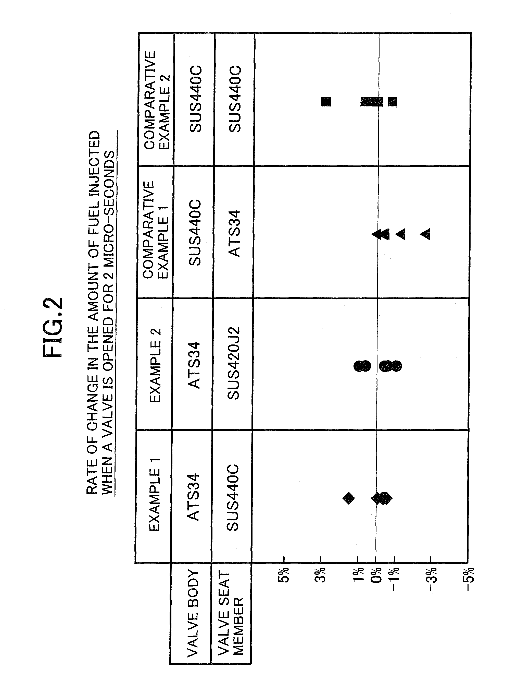
example 1
[0034]The valve body 16 is made of ATS34 stainless steel (hardness HV=780), and the valve seat member 2 is made of SUS440C stainless steel (hardness HV=740).
example 2
[0035]The valve body 16 is made of ATS34 stainless steel (hardness HV=780), and the valve seat member 2 is made of SUS420J2 stainless steel (hardness HV=650 to 700).
Login to View More PUM
 Abstract
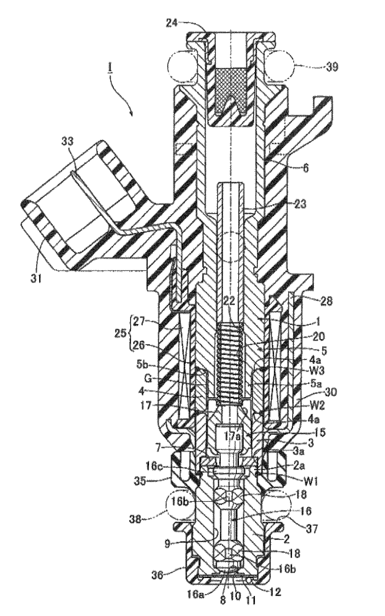
In an electromagnetic fuel injection valve, a valve housing includes: a cylinder-shaped valve seat member having a valve seat in its front end portion; a magnetic cylindrical body coaxially connected to a rear end portion of the valve seat member; a nonmagnetic cylindrical body coaxially and liquid-tightly welded to a rear end of the magnetic cylindrical body; and a hollow cylindrical stationary core coaxially and liquid-tightly welded to a rear end of the nonmagnetic cylindrical body. A valve assembly is housed in the valve housing and includes: a valve body capable of being seated on the valve seat; and a movable core connected to a rear end of the valve body and opposed to a front end of the stationary core. The valve body and the valve seat member are respectively made of different martensitic stainless steels so that a hardness of the valve body is higher than that of the valve seat member. Accordingly, it is possible to provide an electromagnetic fuel injection valve for alcohol fuel which is capable of preventing the adhesive wear from occurring in the seat portion while a valve body and a valve seat member made of martensitic stainless steel are used.
Description
CROSS-REFERENCE TO RELATED APPLICATION[0001]This application claims the priority of Japanese Application No. 2008-177057, filed Jul. 7, 2008, the entire specification, claims and drawings of which are incorporated herewith by reference.BACKGROUND OF THE INVENTION[0002]1. Field of the Invention[0003]The present invention relates to an electromagnetic fuel injection valve, in which: a valve housing includes: a tubular valve seat member having a valve seat in a front end portion thereof; a magnetic cylindrical body coaxially connected to a rear end portion of the valve seat member; a nonmagnetic cylindrical body coaxially and liquid-tightly welded to a rear end of the magnetic cylindrical body; and a hollow cylindrical stationary core coaxially and liquid-tightly welded to a rear end of the nonmagnetic cylindrical body, a valve assembly is housed in the valve housing and includes: a valve body capable of being seated on the valve seat; and a movable core connected to a rear end of the ...
Claims
Login to View More Application Information
Patent Timeline
 Patent Type & Authority Patents(United States)
IPC IPC(8): F16K31/02
CPCF02M61/188F02M2200/9053F02M61/1886F02M51/0664F02M61/1893F02M51/0678F02M61/166
Inventor SUZUKI, KATSUYUKIKATO, GENMIYASHITA, JUNICHITSUNOTA, KENICHI
Owner HITACHI ASTEMO LTD