Damped air bearing

a technology of air bearings and air bearings, which is applied in the direction of bearing cooling, sliding contact bearings, crankshafts, etc., can solve the problems of resonance or instability of air bearing suspension systems, resonance or instability of air bearings, and add to bearing wear and drag, so as to improve air bearing stiffness and overall positioning system accuracy, increase damping, and increase damping

Active Publication Date: 2014-03-04
FLUIDIC MICROCONTROLS
View PDF8 Cites 3 Cited by
  • Summary
  • Abstract
  • Description
  • Claims
  • Application Information

AI Technical Summary

Benefits of technology

[0007]The objective of this invention is to provide air bearings with greatly increased damping, which also then results in improvements in air bearing stiffness and overall positioning system accuracy. In the improved bearing, the air bearing support pad is connected to an output port of a fluidic beam deflection amplifier. The beam deflection amplifier includes a power jet issuing from a nozzle pressurized by an external supply source, a pair of input control ports which create jets at right angles to the power jet such as to deflect the power jet by transfer of momentum, a vented interaction region, and a pair of output ports with a differential output pressure (between the output ports) proportional (i.e., is a function of, and indicative or representative of; approximately proportional, and preferably proportional) to the differential control port pressure (between the control ports). The bearing pad pressure (between the bearing pad and the suspended mass) is proportional to pressure out of the fluidic amplifier positive port and inversely proportional to the gap between the supported body and the bearing pad skirt. The amplifier supply port is pressurized by the external source of supply pressure to create a pressure at the output port to energize (pressurize) the bearing pad, not requiring contamination-sensitive small orifices or porous media to distribute pressurized gas across the surface of the bearing pad. Increased damping is provided by creating pressure signals to the input control ports of the fluidic amplifier which deflect the supply power jet as a function of the velocity of the suspended body. For applications requiring maximum damping, the supply jet centerline is symmetrical to the two output ports to allow for maximum pressure swing. For applications requiring maximum load carrying ability, the supply jet centerline can be offset by approximately one quarter of a jet width toward the positive output port to maximize pressure to the bearing pad.

Problems solved by technology

Damping of gas bearings has typically been derived from the inherent force created from squeezing the viscous gas between the small gaps between the bearing pad and surface of the supported member or by adding coulomb friction, which adds to bearing wear and drag.
This damping is nearly ineffective for gaps greater than 25 microns, where it is often required to operate in high speed rotating machinery design.
The result is resonances or instability in the air bearing suspension system.
Various techniques have been used to adjust the gaps to control damping ratios, but maximum achievable damping is still limited.
However, these techniques are complicated and are not robust enough for industrial automation or high speed rotating machinery applications.
Foil bearings rely on coulomb friction from support springs to provide limited damping, but the resulting damping decreases for increasing excursion amplitudes.

Method used


Image

  • Damped air bearing
  • Damped air bearing
  • Damped air bearing

Examples


Embodiment Construction

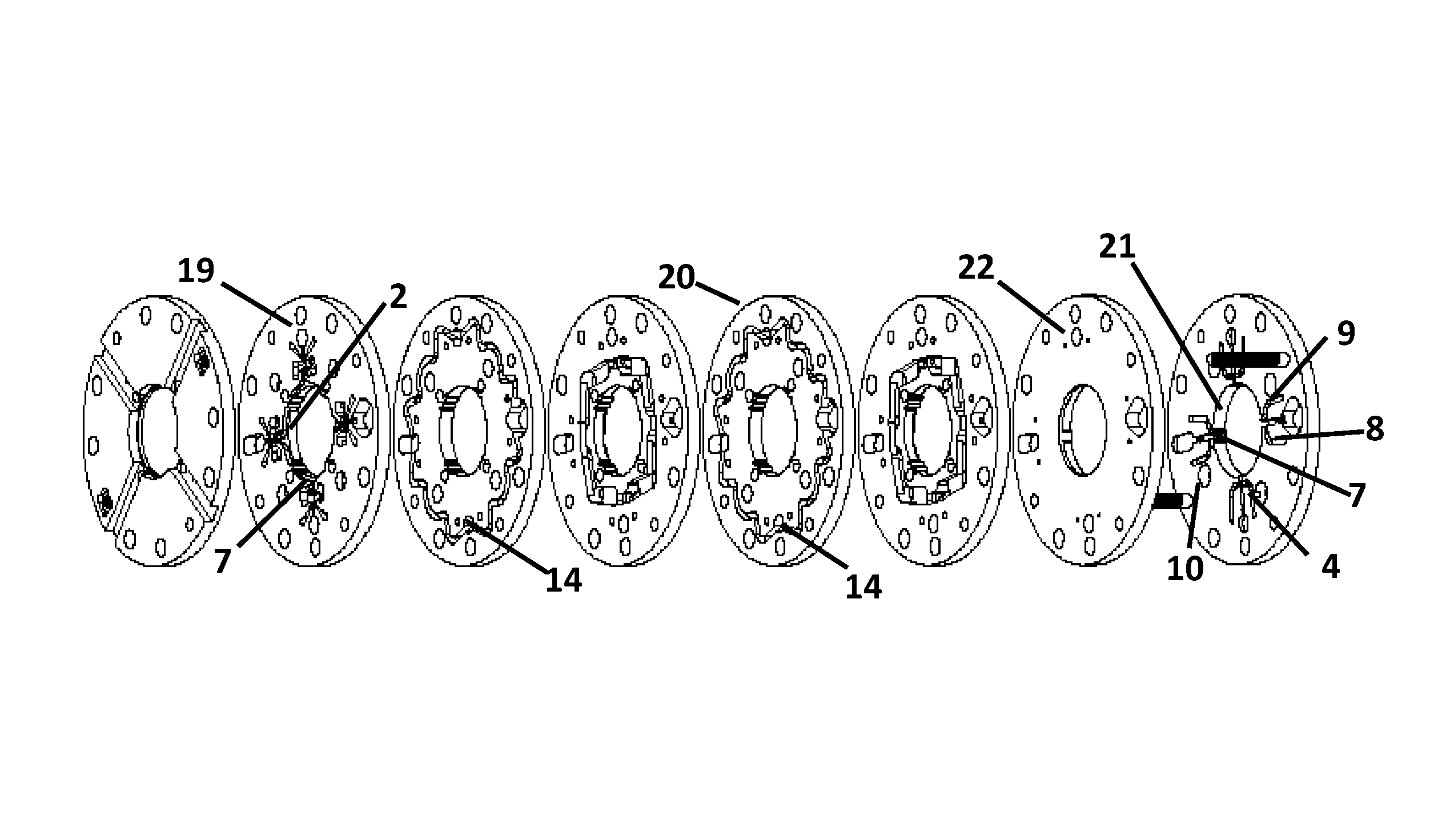
[0017]The actively damped air bearing invention is best described referring to the drawings, wherein the same reference numerals are used identify the same elements throughout the drawings. Air bearings of the subject type are closed loop devices, and, if under damped, are unstable or oscillatory over the desired operating range.

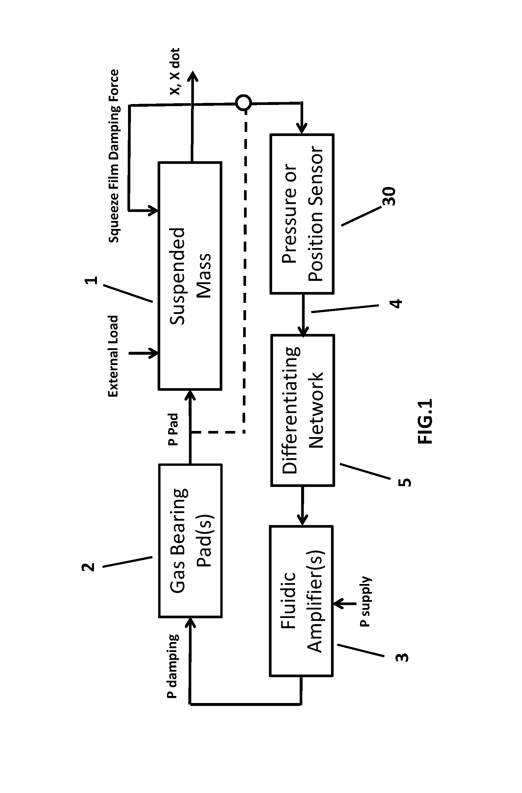
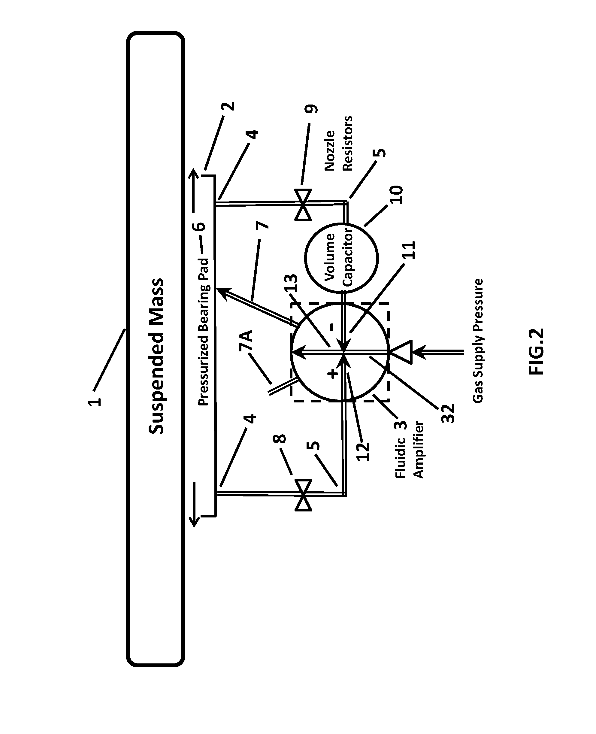
[0018]FIG. 1 is a block diagram showing the elements of a closed loop air bearing with the addition of active fluidic damping. The system includes the mass 1 and external forces or loads on the object to be suspended on the pressurized area of bearing pad 2. The bearing pad 2 is pressurized by the output pressure (P damping) from a beam deflection fluidic amplifier 3 which is powered with a supply pressure (P supply) from an external source of pressurized gas. The output pressure (P damping) of the fluidic amplifier 3 is proportional to the differential pressure signal (P amp-in) applied across its input control ports. A feedback signal 4 to achieve active d...


PUM


Abstract

An air or gas bearing supports a moving mass on a thin column of gas which is partially constrained in a pressurized cavity. The gas to the cavity is supplied through a fluidic amplifier. Pressure in the thin supporting column above the bearing pad, or the position of the mass surface relative to the open end of the pressurized cavity, is sensed. The resulting feedback pressure signal is dynamically compensated to produce a pressure signal to the input ports of the fluidic amplifier which is a function of the velocity of the mass. The compensation network consists of orifices, or flow resistors, and volume cavities, or compressible fluid capacitors. The compensated feedback pressure is amplified by the fluidic amplifier to provide an output pressure to the bearing cavity which is indicative of and nearly proportional to the mass velocity perpendicular to the bearing pad and achieve a high degree of damping without use of extremely small orifices or complicated electromechanical damping means.

Description

INCORPORATION-BY-REFERENCE OF MATERIAL SUBMITTED ON A COMPACT DISC[0001]Not Applicable.STATEMENT REGARDING FEDERALLY SPONSORED RESEARCH OR DEVELOPMENT[0002]Not Applicable.FIELD OF THE INVENTION[0003]This invention relates to aero-static gas bearings and, particularly, how to greatly improve the damping characteristics of these bearings by utilizing compensated fluidic amplifiers to pressurize the bearing pads.BACKGROUND OF THE INVENTION[0004]Aero-static gas bearings use a thin layer of pressurized gas between surfaces to allow relative movement with virtually no friction. This layer of gas is typically only 5 to 25 microns deep. The area of the pad is sized to keep the surfaces separated under their weight and external loads when pressurized. The resulting bearing stiffness is proportional to the energizing pressure supplied to the bearing pad and inversely proportional to the square of gas film depth between the surfaces. A variety of methods have been utilized to evenly distribute...

Claims


Application Information

Patent Timeline
Patent Type & Authority Patents(United States)
IPC IPC(8): F16C3/16F16C17/10F16C32/06
CPCF16C29/025F16C32/06F16C17/10F16C3/16F16C32/0622
Inventor FREDERICK, GARY, L.
Owner FLUIDIC MICROCONTROLS
Why Eureka
Try Eureka