Dual leaf suspension for vehicle drive arrangement

a technology of suspension and leaf, applied in the direction of loading/unloading vehicle arrangment, transportation and packaging, transportation items, etc., can solve the problems of high unsprung mass of the drive system, coupled left/right wheel motion, and known system suffering from vertical deflection and wind-up, so as to facilitate the adjustment of the effective spring rate

Active Publication Date: 2014-03-11
RASSINI SA DE CV
View PDF86 Cites 13 Cited by
  • Summary
  • Abstract
  • Description
  • Claims
  • Application Information

AI Technical Summary

Benefits of technology

[0024]In a highly advantageous embodiment of the invention, there are further provided first and second displaceable pivot coupling arrangements for coupling the respective second ends of the first and second secondary leaf springs to the chassis. The displaceable pivot coupling arrangements facilitate adjustment of the effective spring rate of the secondary leaf springs.
[0025]In other embodiments, there are provided first and second displaceable fulcrum arrangements, also for facilitating the varying of the respective spring rates of the first and second secondary leaf springs.

Problems solved by technology

There are a number of problems with this form of drive arrangement.
First, this drive system is characterized by high unsprung mass.
Additionally, the use of a solid axle results in coupled left / right wheel motion.
During heavy cornering and fast acceleration, this known system suffers from vertical deflection and wind-up.
However, the known parallel leaf spring arrangement employs a solid axle, and therefore does not provide the benefits of independent suspension.
In addition, this known arrangement is plagued with the disadvantage of high unsprung mass.
However, the de Dion tube adds unsprung weight.

Method used


Image

  • Dual leaf suspension for vehicle drive arrangement
  • Dual leaf suspension for vehicle drive arrangement
  • Dual leaf suspension for vehicle drive arrangement

Examples


Embodiment Construction

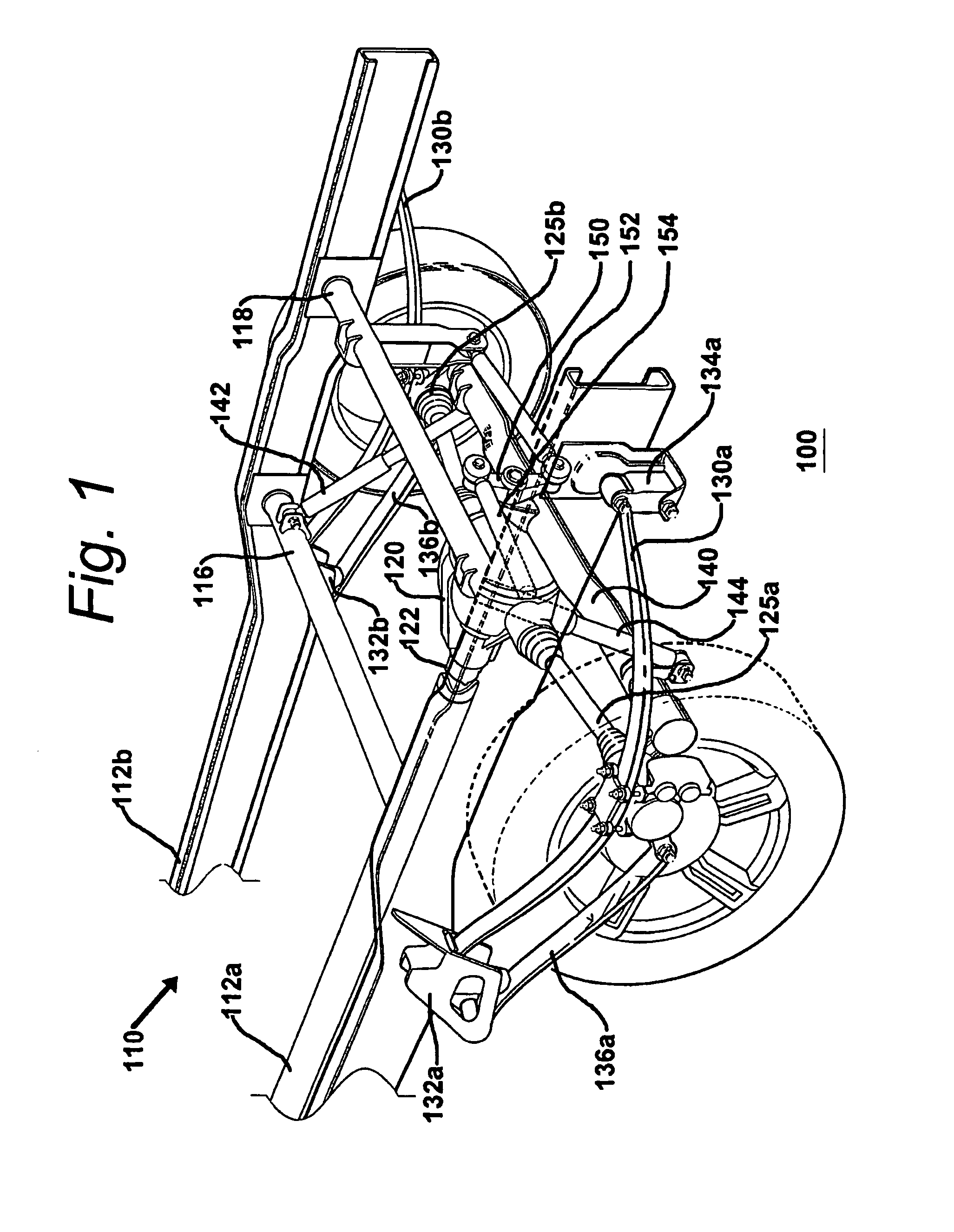
[0049]FIG. 1 is a perspective representation of a specific illustrative embodiment of the invention. As shown in this figure, a vehicle suspension system 100 has a chassis that is generally designated as chassis 110. The chassis has a pair of substantially parallel chassis rails 112a and 112b that are coupled to one another by cross-braces 116 and 118.

[0050]A differential drive arrangement 120 is fixedly coupled to the chassis and converts the rotary motion of a drive shaft 122 to substantially orthogonal rotary motion at half shafts 125a and 125b. Each half shaft has an associated pair of universal joints (not specifically designated) that are arranged to be proximal and distal with respect to the differential drive arrangement. Thus, the half shafts, each of which has an associated longitudinal axis (not shown), accommodate transaxial motion, particularly by operation of the proximal universal joints.

[0051]Half shafts 125a and 125b are shown to be coupled at their distal ends to r...


PUM


Abstract

A vehicle drive arrangement for a vehicle of the type having differential power transmission arrangement that converts the rotatory motion of the rotatory power shaft to rotatory motion of first and second drive shafts disposed substantially orthogonal the rotatory power shaft. Primary leaf springs are each coupled at their respective centers to respective drive shafts by pivotal arrangements. The first and second primary springs may include helical springs that are used in place of, or in combination with, the primary leaf springs. Secondary leaf springs may be splayed and therefore need not be arranged parallel to the primary leaf springs. Control over vehicle kinematics is enhanced by configuring the resilience of a fulcrum bumper using resilient, rheological, or active systems. An active system will control vehicle height while stationary to facilitate loading and unloading of the vehicle.

Description

REFERENCE TO OTHER APPLICATIONS[0001]This application is a US national stage filing under 35 U.S.C. §371 of International Application No. PCT / US2007 / 014290 filed on Sep. 18, 2007 and claims the benefit under 35 U.S.C. §119(e) of U.S. Provisional Patent Application Ser. No. 60 / 814,518, filed on Jun. 16, 2006; U.S. Provisional Patent Application Ser. No. 60 / 900,796 filed on Feb. 7, 2007; and U.S. Provisional Patent Application Ser. No. 60 / 921,881 filed on Apr. 3, 2007. The disclosures in these provisional patent applications are incorporated herein by reference.BACKGROUND OF THE INVENTION[0002]1. Field of the Invention[0003]This invention relates generally to suspension systems for vehicles, and more particularly, to a leaf suspension arrangement that is useable with independent and semi-independent suspension systems.[0004]2. Description of the Related Art[0005]Leaf spring systems have for many years been used for the suspension of wheeled vehicles. The central element of a leaf spri...

Claims


Application Information

Patent Timeline
Patent Type & Authority Patents(United States)
IPC IPC(8): B60G17/02B60G11/04B60G11/10
CPCB60G2200/30B60G2204/4306B60G2202/112B60G11/12B60G2204/1482B60G11/113B60G2204/121B60G17/023B60G2204/148B60G2204/4502B60G11/10B60G5/047
Inventor JURIGA, JAMES, ANDREW
Owner RASSINI SA DE CV
Why Eureka
Try Eureka