
Method, system and apparatus for signal generation and message transmission in broadband wireless communications

a technology of broadband wireless communication and signal generation, applied in the field of transmission information, can solve the problems of significant inter-cell interference, insufficient flexibility and convenience in allocation and scheduling of resources, and the user terminal at the edge of the cell communication performance may be degraded sharply, so as to facilitate networking, improve the capacity and performance of the system, and ensure the effect of transmission efficiency

Active Publication Date: 2014-03-11
DATANG MOBILE COMM EQUIP CO LTD
View PDF13 Cites 1 Cited by
  • Summary
  • Abstract
  • Description
  • Claims
  • Application Information

AI Technical Summary

Benefits of technology

The invention provides a method and device for generating and transmitting signals in wireless communication systems. It can effectively and reliably transmit information over multiple access channels, improving system capacity and performance. The invention addresses issues of resource allocation and interference control, including intra-cell and inter-cell interference, to provide a solution for efficient wireless communication. The technical effects of the invention are improved system capacity and performance.

Problems solved by technology

Unfortunately, the DFT-S OFDM multiple access still has the following drawbacks.
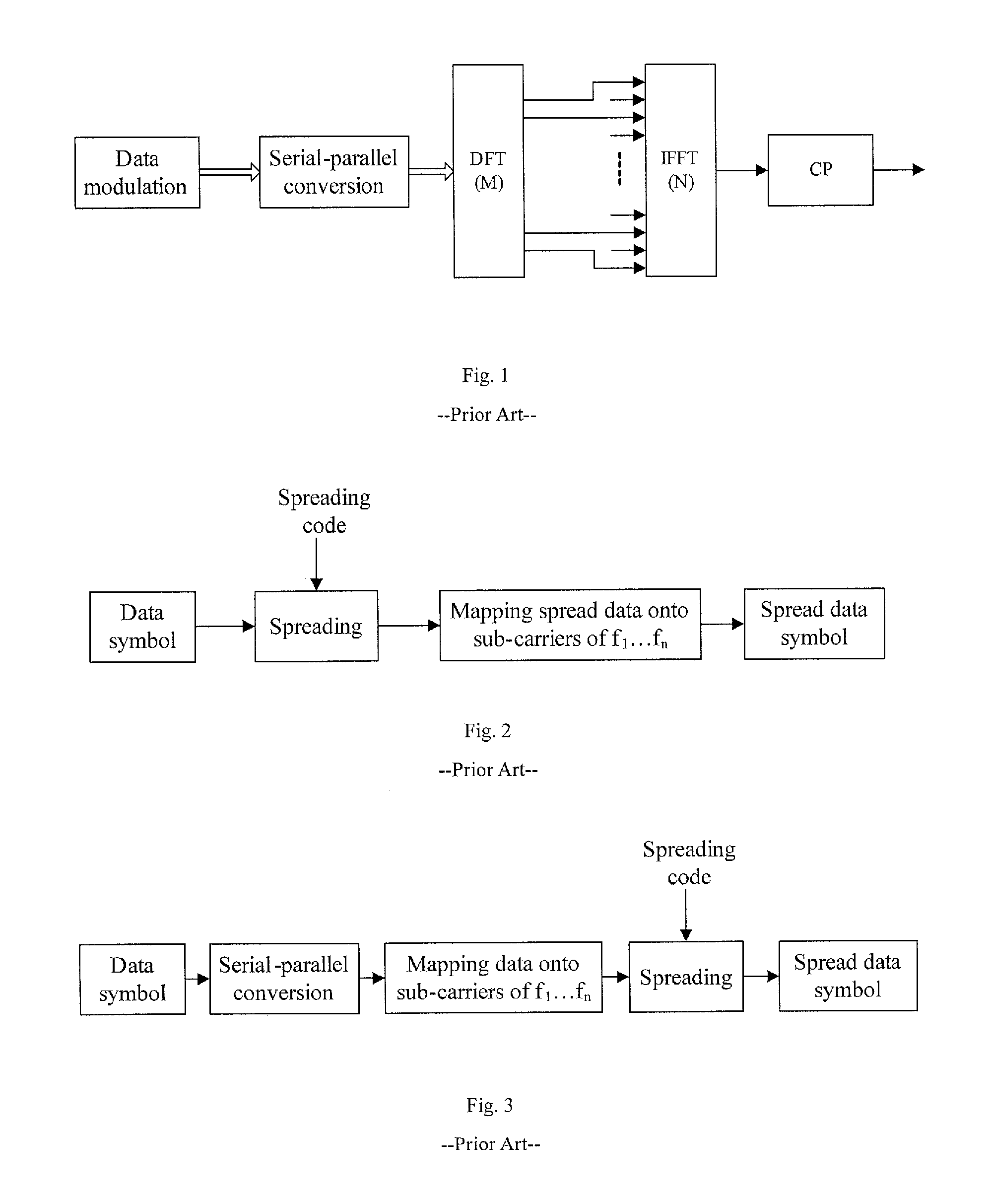
In an application of the uplink DFT-S OFDM multiple access to a cellular mobile communication system, networking at the same frequency may result in significant inter-cell interference because users in different cells with reception and transmission of data over the same sub-carrier may possibly interfere reception and transmission of data of a user terminal in an adjacent cell.
Especially at an edge of a cell, a user terminal at a relatively short distance from another cell is subject to a relatively strong signal arriving from the other cell, and during reception and transmission of data at the user terminal, serious mutual interference may arise between signals of the adjacent cells, so that communication performance of the user terminal at the edge of the cell may be degraded sharply.
Like the CDMA, however, the foregoing solutions are demanding for temporal and frequency synchronization of a signal, where the same time and frequency resources have to be occupied for data of the cells to detect signals of users of the cells, thus requiring coordination and scheduling of the resources between the cells.
In the foregoing several solutions, neither allocation and scheduling of resources nor coordinated control of interference is sufficiently flexible and convenient; multiple access interference has to be eliminated at the receiver in a complicated process at a high cost; and channel fading and interference may also give rise to a sudden error of some symbols.

Method used


Image

  • Method, system and apparatus for signal generation and message transmission in broadband wireless communications
  • Method, system and apparatus for signal generation and message transmission in broadband wireless communications
  • Method, system and apparatus for signal generation and message transmission in broadband wireless communications

Examples


first embodiment

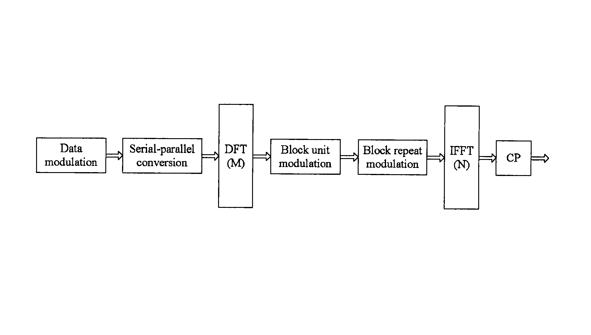
[0066]Specifically, a structural block diagram of a transmission device in the first embodiment is as illustrated in FIG. 9, where data for transmission is modulated at three stages into a final signal for transmission, a first of which is transmission data modulation performed at a transmission data modulation module which modulates and segments the data for transmission to generate a Data symbol Block (DB), a second of which is block unit modulation performed at a block unit modulation module which modulates the generated data symbol block to generate a Block Unit (BU), where generation of the block unit is to fill respectively a generated sequence of data symbols (which is referred to as data stream) into time and frequency points corresponding to the block unit, for example, in an interleaving process by an interleaver, and in this embodiment, the data symbol block is put directly into the block unit, and the third of which is block repeat modulation performed at a block repeat ...

second embodiment

[0067]A structural block diagram of a transmission device in the second embodiment is as illustrated in FIG. 10, where data for transmission is modulated at three stages into a final signal for transmission, a first of which is transmission data modulation performed at a transmission data modulation module which modulates and segments the data for transmission to generate a data symbol block, a second of which is block repeat modulation performed at a block repeat modulation module which weights and repeats the data symbol block; and the third of which is block unit modulation performed at a block unit modulation module which maps data symbol blocks obtained by the weighting and repeating into block units at specified time and frequency locations, where mapping is to fill respectively the data symbol blocks sequentially into time and frequency points corresponding to the respective block units in a specific sequence, for example, in an interleaving process by an interleaver, alterna...


PUM


Abstract

Method for signal generation in broadband wireless communications, comprises: A. modulating, segmenting and serial-parallel converting the signal data to be transmitted, then computing DFT of the serial-parallel converted data so as to transfer them to frequency domain; B. performing block unit modulating processing and block repeat modulating processing on the frequency domain data, then mapping the block units to assigned time-frequency positions; C. computing IFFT of the mapped block units, then adding them to the cycle prefix, thus the random sequences in time domain are generated. Apparatus for signal generation, Method and system for message transmission in broadband wireless communications are also disclosed. The problem of resource allocation and scheduling, and problem of interference coordination and control are solved, the throughput and performance of communication system are greatly improved.

Description

CROSS REFERENCE TO RELATED APPLICATIONS[0001]This application is a national phase filing under 35 U.S.C. §371 of International application number PCT / CN2008 / 001932, filed Nov. 26, 2008, which claims priority from Chinese Application No. 200710178100.3, filed Nov. 26, 2007. The entire contents of the prior applications are incorporated herein by reference in their entirety.FIELD OF THE INVENTION[0002]The present invention relates to the field of transmitting information and particularly to a method and device for generating a signal and a method and device for transmitting information in broadband wireless communications.BACKGROUND OF THE INVENTION[0003]Along with rapid development of a mobile communication technology, broadband wireless communications becomes a predominant development trend of future mobile communications. The International Telecommunication Union (ITU) has further provided a more powerful and advanced mobile communication system, i.e., IMT-Advanced, based upon the ...

Claims


Application Information

Patent Timeline
Patent Type & Authority Patents(United States)
IPC IPC(8): H04J11/00
CPCH04L5/0021H04L5/0019H04L5/0044
Inventor SUN, SHAOHUIYU, YANGWANG, YINGMINXIE, YONGBIN
Owner DATANG MOBILE COMM EQUIP CO LTD
Learn More