Lane centering fail-safe control using differential braking

a technology of fail-safe control and differential braking, applied in the direction of non-deflectable wheel steering, underwater vessels, braking components, etc., can solve the problems of lc system failure, eps system failure, and inability to provide automatic steering control

Active Publication Date: 2014-03-11
GM GLOBAL TECH OPERATIONS LLC
View PDF12 Cites 21 Cited by
  • Summary
  • Abstract
  • Description
  • Claims
  • Application Information

AI Technical Summary

Benefits of technology

[0013]A method, system and non-transitory computer-readable medium according to an embodiment of the invention, may determine a yaw moment needed by the LC control system. Yaw moment (Δτ) for a vehicle represents an amount of force against the vehicle's center of gravity which may be applied to a vehicle to turn or pivot the vehicle and change its heading orientation. Based on that determined yaw moment, the method may calculate a sequence of differential braking forces to be applied to the wheels of the vehicle. The system and method may maintain the vehicle motion according to the sequence of differential braking forces for a period, for example, the next delta (Δ) t seconds (e.g. the next 3 seconds, tunable), allowing the driver to get back to the steering control within the period.
[0014]In a method, system and non-transitory computer-readable medium according to an embodiment of the present invention, a lane centering system may generate and the fail-safe system may use elements that may determine a desired path and a predicted path for a moving vehicle. For example, a lane mark detection system of a lane centering system may recognize lane marks in a road, dividing the road into lanes. A desired path generation module of a lane centering system may generate a smooth desired path for a lane centering according to vehicle dynamics (such as vehicle mass, inertia, dimensions, etc.) and the lane marks detected (such as generating a smooth path from the current vehicle position to the center of the lane as an example). A predicted path prediction system of a lane centering system may further generate the vehicle's predicted future path based on current vehicle dynamics such as vehicle speed, yaw rate, and the steering angle (the amount the front wheels of the car are turned from being parallel with the sides of the car).
[0017]In applying a differential braking control to maintain lane control, the fail-safe system may use the desired path and predicted path information available (e.g. from elements of the lane controller system or generated from fail-safe system sources) to find a sequence of braking commands for the available wheels of the vehicle. For example, the fail-safe system may find a braking command sequence such as, Fleft front wheel(t), Fright front wheel(t), Fleft rear wheel(t), Fright rear wheel(t), on a time interval (such as [0, Δt]) that minimizes the difference of the desired path and the predicted path of the vehicle.
[0018]A fail-safe differential braking controller according to an embodiment of the invention may, for example, generate braking commands for each wheel to minimize orientation and offset errors (e.g. differences in vehicle heading and lateral offset position) between the vehicle's desired path and the vehicle's predicted path.
[0019]To minimize such orientation and offset errors between the vehicle's desired path and predicted path, the fail-safe differential braking controller according to an embodiment of the invention may use a cost function, where the orientation and offset errors between the vehicle's desired path and predicted path are minimized according to a yaw moment value for the vehicle.
[0029]With the force distribution determined, the fail-safe differential braking controller may access a differential braking system to have the forces applied the brakes. The fail-safe differential braking controller may, for example, generate a sequence of braking commands for the available wheels of the vehicle on a interval (for example Δt seconds, e.g. 3 seconds, a value which may be tuned or changed) to provide time for the operator of the vehicle to get back steering control.

Problems solved by technology

Where the LC system uses an electrical power steering (EPS) system for its automatic steering control, it is possible that the EPS system could fail (for example, by communication system failure, control processor crash, mechanical problem in the steering system, etc.).
In such a situation, an LC system could not, upon the failure, provide automatic steering control, because the system's ability to control the vehicle's steering would be cut-off.
In some circumstances, a failure of an EPS system may cause the front wheels of the system to lock in their current steering angle position, causing further risk of vehicle accident.
Thus, a challenge to safety is presented in an LC system in the event of a failure such as an EPS system failure.

Method used


Image

  • Lane centering fail-safe control using differential braking
  • Lane centering fail-safe control using differential braking
  • Lane centering fail-safe control using differential braking

Examples


Embodiment Construction

[0039]In the following detailed description, numerous specific details are set forth in order to provide a thorough understanding of the invention. However, it will be understood by those skilled in the art that the present invention may be practiced without these specific details. In other instances, well-known methods, procedures, and components have not been described in detail so as not to obscure the present invention.

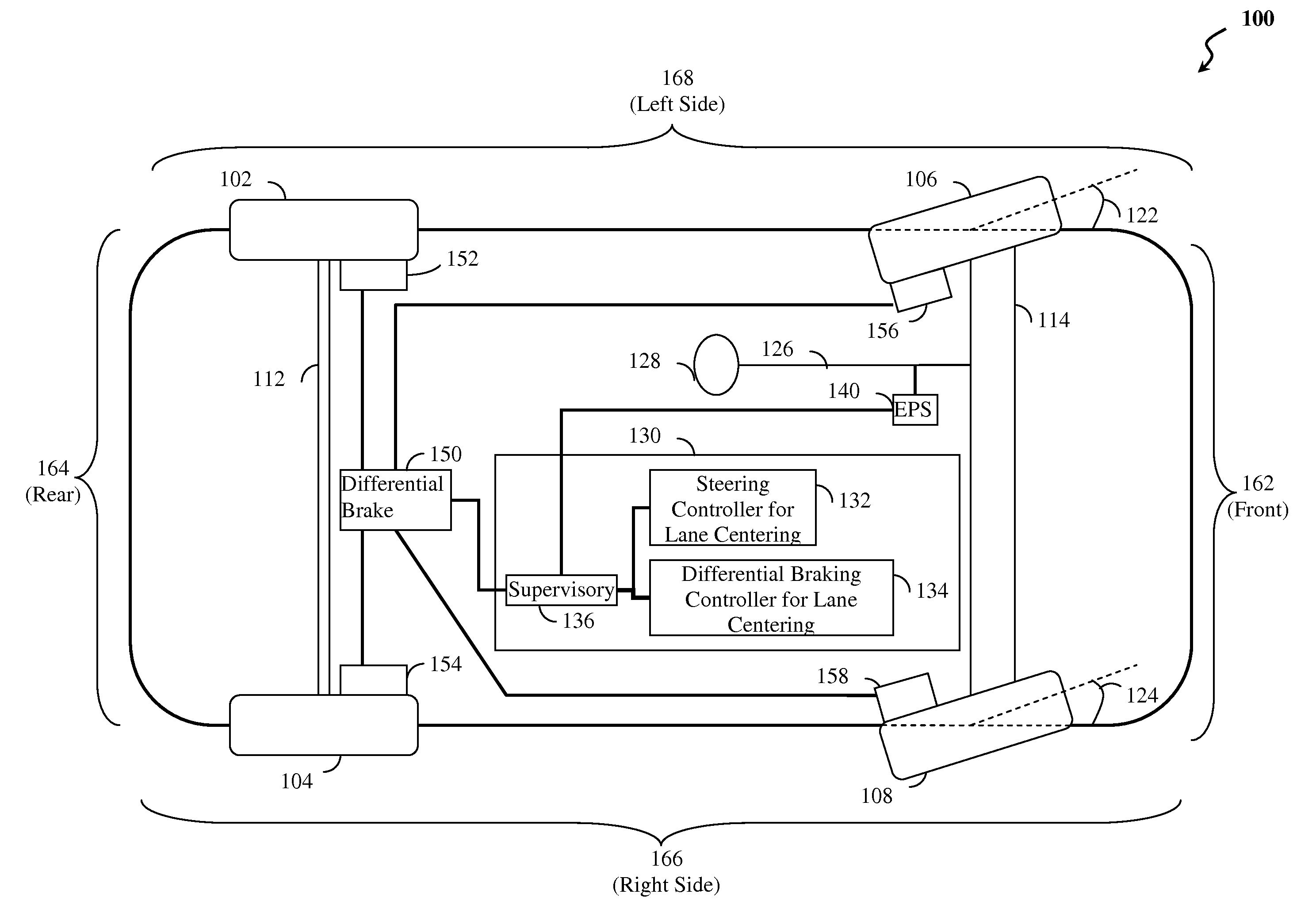
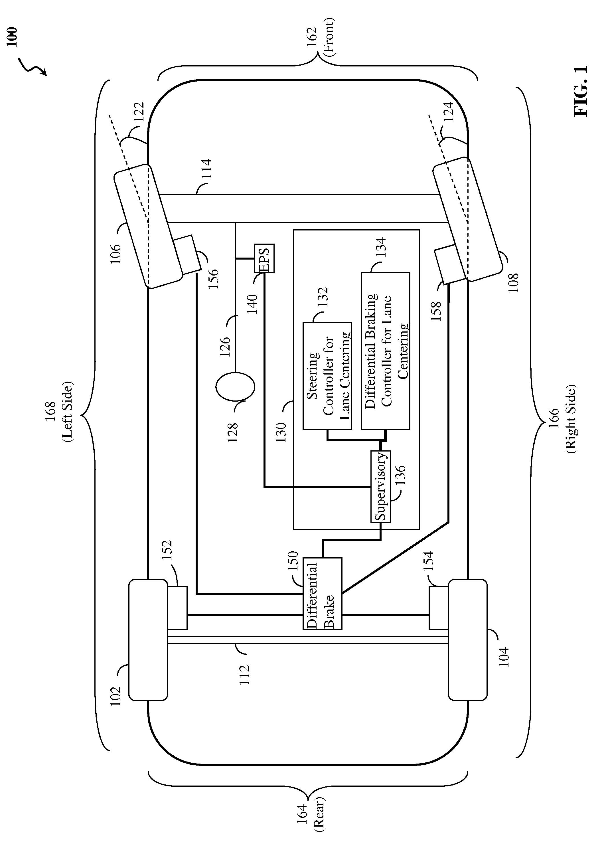
[0040]Reference is made to FIG. 1 which illustrates elements of a lane centering (LC) system with fail-safe differential braking according to an embodiment of the present invention. FIG. 1 depicts vehicle 100, which may be an automobile or other vehicle, having front side 162, rear side 164, right side 166 and left side 168 (e.g. viewing the vehicle from above). Vehicle 100 is shown with wheels, e.g. left rear wheel 102, right rear wheel 104, left front wheel 106, right front wheel 108. In other examples, vehicles having fewer wheels, e.g. 3, or more wheels, e.g. ...


PUM


Abstract

Method, system and non-transitory computer-readable medium for fail-safe performance of a lane centering system. An electrical power steering (EPS) system of a vehicle is monitored for a failure and operation of the lane centering system is switched to a differential braking controller to output differential braking commands to a differential breaking system upon determining that a failure of the EPS system has occurred, where the output braking commands direct the differential braking system to apply force a brake for a wheel of vehicle, such by the applied braking force the vehicle follows a desired path determined for a lane centering operation.

Description

TECHNICAL FIELD[0001]The present disclosure relates generally to the field of autonomous and semi-autonomous driving control systems, and, more particularly, to the fields of lane centering control systems and fail-safe controls for lane centering control systems.BACKGROUND OF THE INVENTION[0002]Increasingly, vehicles are being equipped with autonomous and / or semi-autonomous driving mechanisms providing automated diving controls where less driver intervention is required. Though only a few vehicles today may have been created to be fully autonomous (i.e. capable of driving from point A to point B without any driver intervention), many commercially-available vehicles today may employ autonomous and semi-autonomous features.[0003]Cruise control systems, for example, have long been available where a driver sets the speed of the vehicle and the vehicle automatically controls the throttle. Adaptive cruise control systems have been developed too, where the system maintains a set speed and...

Claims


Application Information

Patent Timeline
Patent Type & Authority Patents(United States)
IPC IPC(8): G06F19/00B62D5/04
CPCB60T2201/08B60T2270/402B60W2720/14B60W2710/182B60W30/12B60W50/029B60T2260/02B62D15/025B60W2050/0025B62D9/005B60T8/17557
Inventor LEE, JIN-WOOMOSHCHUK, NIKOLAI K.CHEN, SHIH-KEN
Owner GM GLOBAL TECH OPERATIONS LLC
Why Eureka
Try Eureka