Hybrid prefilming airblast, prevaporizing, lean-premixing dual-fuel nozzle for gas turbine combustor

a gas turbine and combustor technology, applied in the ignition of the turbine/propulsion engine, engine starters, lighting and heating apparatus, etc., can solve the problems of increased nox emissions, poor reliability, and design problems such as high emissions

Inactive Publication Date: 2014-03-18
GENERAL ELECTRIC CO
View PDF13 Cites 18 Cited by
  • Summary
  • Abstract
  • Description
  • Claims
  • Application Information

AI Technical Summary

Problems solved by technology

When fuel is injected in air for combustion in a combustion chamber of the gas turbine, high temperature regions are formed locally in the combustion gas, which increase NOx emissions.
Previous designs have used multi-point atomizer injection inside the premixer, but these designs have suffered from high emissions due to maldistribution of the fuel and from poor reliability due to internal (in the fuel passages) and external (on the premixer walls) fuel coking.

Method used


Image

  • Hybrid prefilming airblast, prevaporizing, lean-premixing dual-fuel nozzle for gas turbine combustor
  • Hybrid prefilming airblast, prevaporizing, lean-premixing dual-fuel nozzle for gas turbine combustor
  • Hybrid prefilming airblast, prevaporizing, lean-premixing dual-fuel nozzle for gas turbine combustor

Examples


Embodiment Construction

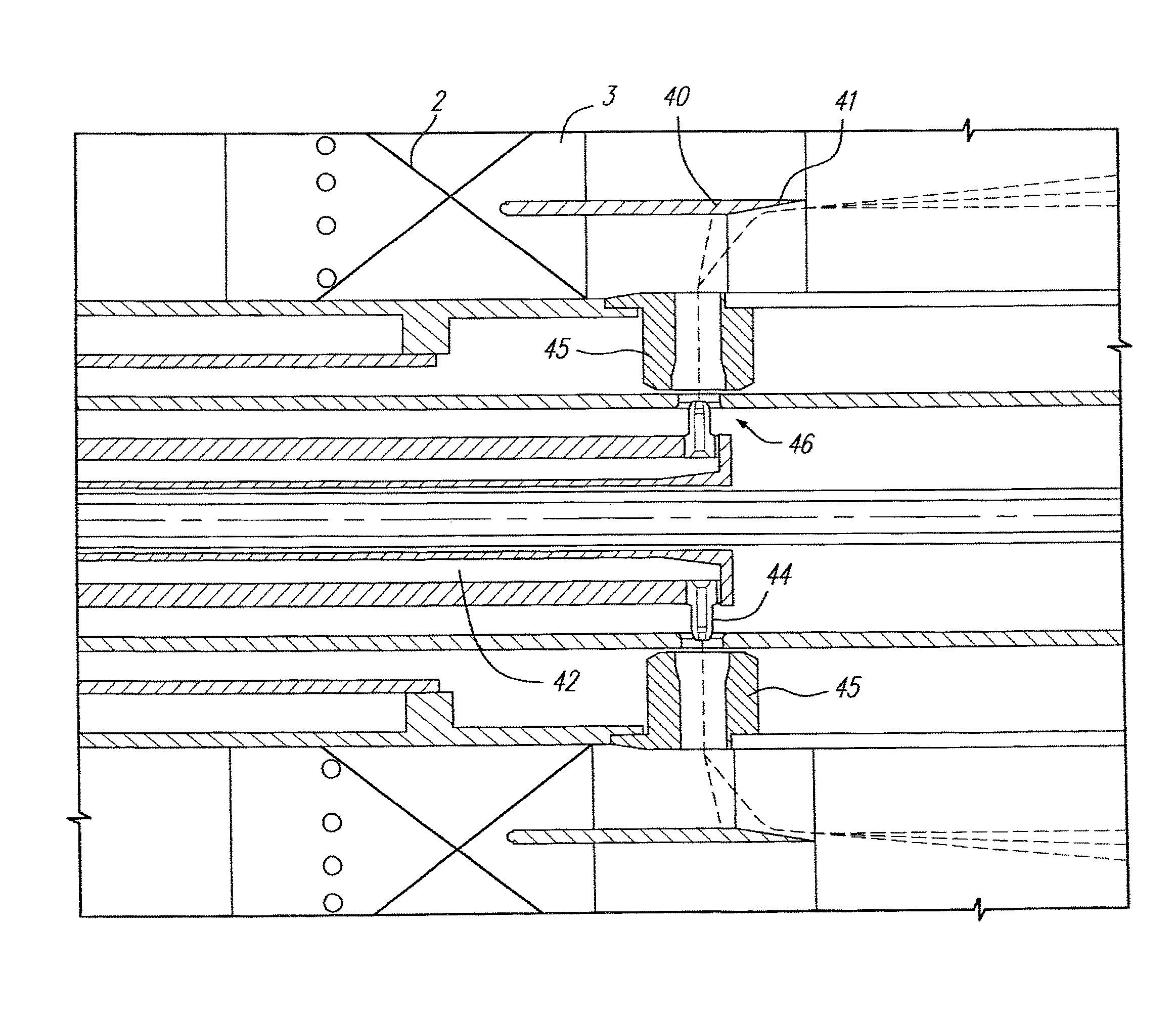
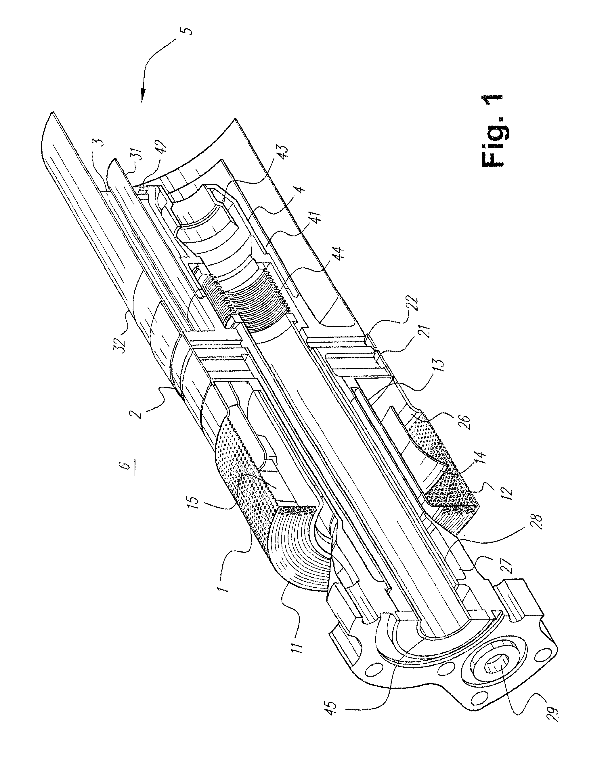
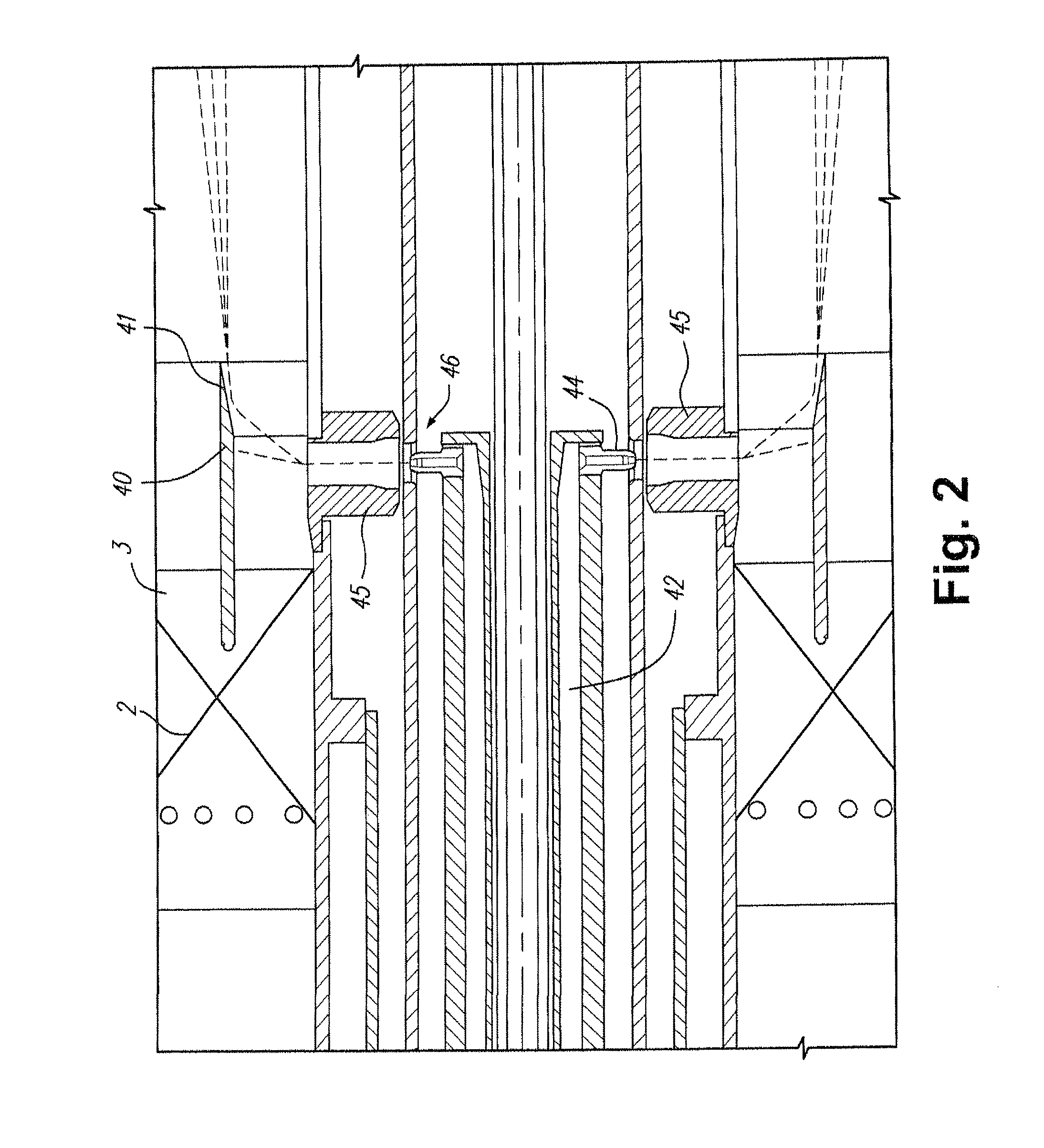
[0010]FIG. 1 is a cross-section through an exemplary burner for a gas turbine. In practice, an air atomized liquid fuel nozzle is installed in the center of the burner assembly to provide dual fuel capability. The liquid fuel nozzle assembly has been omitted from FIG. 1 for clarity. The burner assembly is divided into four regions by function including an inlet flow conditioner 1, an air swirler assembly with natural gas fuel injection (referred to as a swozzle assembly) 2, an annular fuel air mixing passage 3, and a central diffusion flame natural gas fuel nozzle assembly 4.

[0011]Air enters the burner from a high pressure plenum 6, which surrounds the entire assembly except the discharge end, which enters the combustor reaction zone 5. Most of the air for combustion enters the premixer via the inlet flow conditioner (IFC) 1. The IFC includes an annular flow passage 15 that is bounded by a solid cylindrical inner wall 13 at the inside diameter, a perforated cylindrical outer wall 12...


PUM


Abstract

A dual fuel nozzle for a gas turbine combustor includes a hub defining a fuel inlet and a plurality of liquid fuel jets disposed at a downstream end of the hub. The fuel jets are oriented to eject liquid fuel radially outward from the hub. An annular air passage includes a swirler that imparts swirl to air flowing in the annular air passage, and a splitter ring is disposed in the annular air passage and surrounds the plurality of liquid fuel jets. The nozzle allows liquid fuels to be injected into a swirling annular airstream and then atomized, dispersed and vaporized inside a lean premixing dual fuel nozzle for a gas turbine combustor.

Description

BACKGROUND OF THE INVENTION[0001]The invention relates to a dual-fuel nozzle in a gas turbine combustor and, more particularly, to a hybrid prefilming airblast, prevaporizing, lean-premixing dual-fuel nozzle for a gas turbine combustor that allows liquid fuels to be injected from a removable breech-loaded centerbody stick and then atomized, dispersed, and vaporized.[0002]When fuel is injected in air for combustion in a combustion chamber of the gas turbine, high temperature regions are formed locally in the combustion gas, which increase NOx emissions. Previous designs have used multi-point atomizer injection inside the premixer, but these designs have suffered from high emissions due to maldistribution of the fuel and from poor reliability due to internal (in the fuel passages) and external (on the premixer walls) fuel coking.BRIEF DESCRIPTION OF THE INVENTION[0003]In an exemplary embodiment, a dual fuel nozzle for a gas turbine combustor includes an annular air passage and a swirl...

Claims


Application Information

Patent Timeline
Patent Type & Authority Patents(United States)
IPC IPC(8): F02G3/00F02C1/00
CPCF23R3/36F23R3/14F23D2900/11101F23D2900/14004F23R3/286
Inventor BOARDMAN, GREGORY ALLENCHILA, RONALD JAMESHUGHES, MICHAEL JOHNSTEWART, JASON THURMAN
Owner GENERAL ELECTRIC CO
Why Eureka
Try Eureka