Centrifuge nozzle and method and apparatus for inserting said nozzle into a centrifuge bowl

a centrifuge and nozzle technology, which is applied in the direction of centrifuges, combustion types, lighting and heating apparatuses, etc., can solve the problems of improper nozzle orientation, difficulty in removing the nozzle from the bowl, damage to one or both of the nozzle and the bowl, etc., to reduce power requirements, smooth fluid transfer, and flexibility.

Active Publication Date: 2014-03-18
ALFA LAVAL CORP AB
View PDF17 Cites 8 Cited by
  • Summary
  • Abstract
  • Description
  • Claims
  • Application Information

AI Technical Summary

Benefits of technology

[0015]One advantage of the present invention is that because an outwardly projecting dovetail-shaped end surface is employed by the nozzle rather than the conventional screwdriver slot, there is more material at the nozzle end allowing the nozzle outlet to be moved farther out along the nozzle body. This in turn allows for greater flexibility in adjusting the discharge angle of the nozzle relative to the rotor bowl. Optimization of the discharge angle can result in significant reductions in power requirements to operate the centrifuge.
[0016]The additional material at the nozzle end that allows the nozzle outlet to be moved farther out along the nozzle body allows for the passageway between the nozzle inlet and the nozzle outlet to be of a larger radius than it was in conventional designs. A larger radius passageway means that the fluid deflected through the nozzle is subject to less drastic directional changes, which allow for smoother fluid transfer through the nozzle. Accordingly, the turbulence of the flow is reduced, which enables the nozzle to experience less wear.
[0017]Another advantage of the present invention is that the use of the mating dovetail-shaped slot and projection allows force to be exerted on the nozzle by the insertion and extraction tool when the nozzle is being removed from the rotor bowl. More specifically, the nozzle can be pulled from rotor bowl when removal of the nozzle is desired. This was heretofore not possible when employing the conventional screwdriver slot because the screwdriver could not be releasably attached to the nozzle. Accordingly, time is saved when removing or installing nozzles. In addition, damage to the rotor bowl, which usually results from attempting to pry a nozzle from the bowl, is avoided.

Problems solved by technology

Sometimes, due to wear or other maintenance issues, it is necessary to remove the nozzles from the bowl.
This can be problematic in that the nozzles are typically held in the bowl via the frictional engagement of a portion of the nozzle with a portion of the bowl.
However, since the screwdriver used to turn the nozzle is unable to exert a pulling force on the nozzle it is often quite difficult to remove the nozzle from the bowl.
Generally, resort has been had to prying the nozzle from the bowl which can result in damage to one or both of the nozzle and the bowl.
Another problem sometimes occurs when inserting the nozzle into the bowl.
By employing the above-described slot and screwdriver to turn the nozzle into the frictional fit, it is possible to not fully rotate the nozzle relative to the bowl, thereby resulting in an improper nozzle orientation.
Still another problem associated with the above-described prior art nozzles results from there being insufficient material at the end of a nozzle to accommodate the slot for the screwdriver.
This results in the nozzle discharge having to be positioned in a less than optimal location and orientation (i.e., closer to the inlet of the nozzle such that the flow path between the inlet and the nozzle outlet of the discharge has a relatively tight radius or such that the fluid is dispelled substantially radially from the nozzle).
Even when the above-described prior art nozzles are properly positioned, large amounts of horsepower are required to drive the centrifuge.
A drawback of the above-described nozzle is that the slot does not allow the nozzle discharge to be located closer to the outermost surface of the nozzle.
This in turn results in a less than optimal nozzle discharge angle relative to the periphery of the bowl.

Method used


Image

  • Centrifuge nozzle and method and apparatus for inserting said nozzle into a centrifuge bowl
  • Centrifuge nozzle and method and apparatus for inserting said nozzle into a centrifuge bowl
  • Centrifuge nozzle and method and apparatus for inserting said nozzle into a centrifuge bowl

Examples


Embodiment Construction

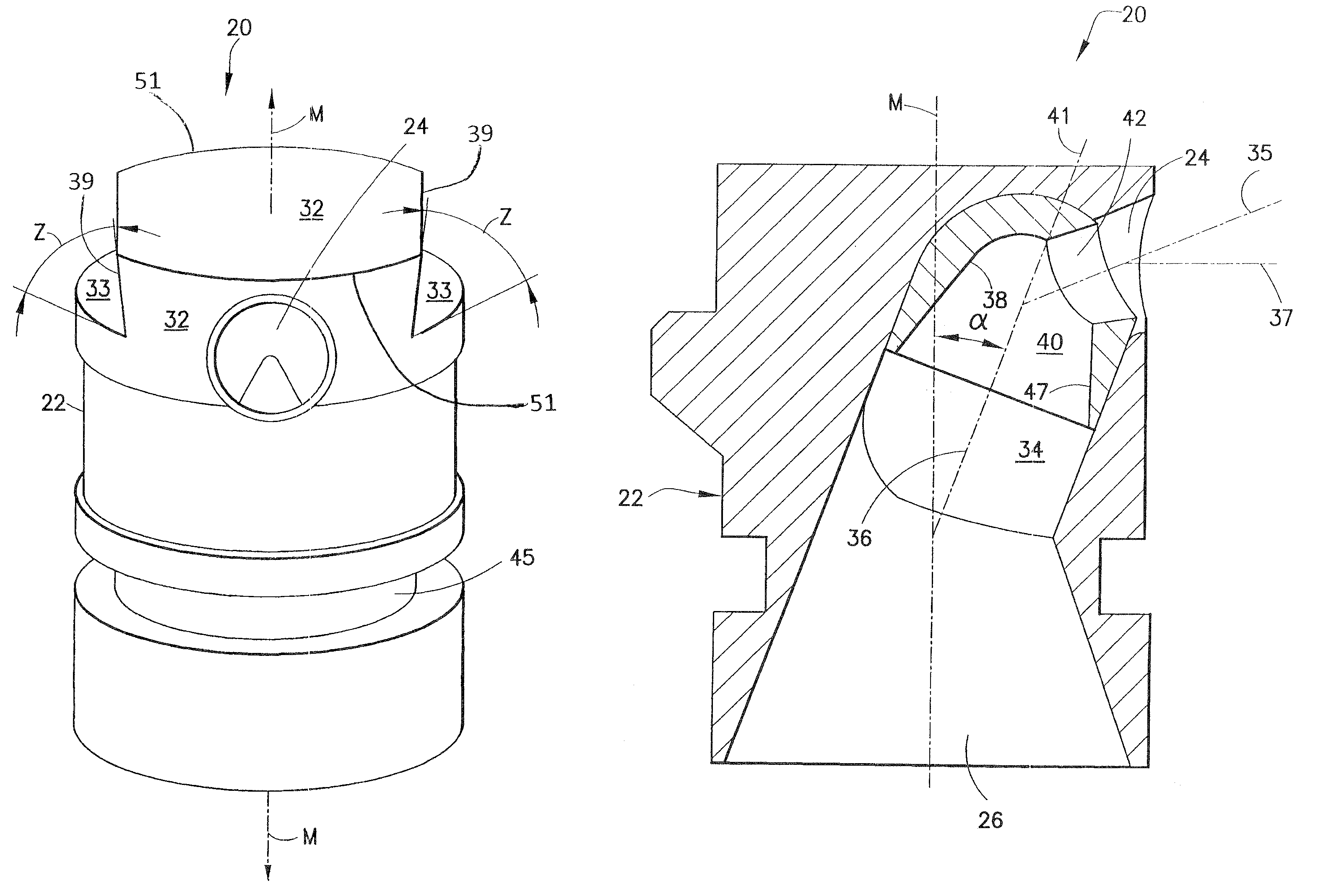
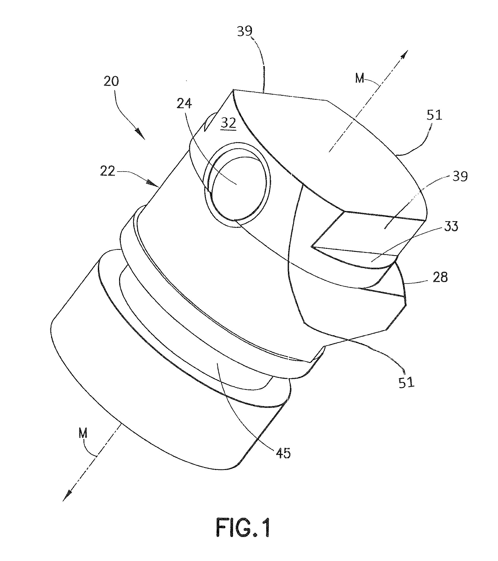
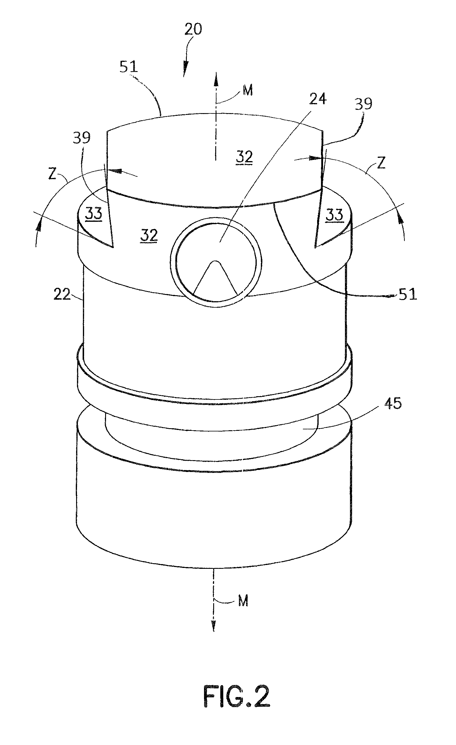
[0030]As shown in FIGS. 1-3, a centrifuge nozzle made in accordance with the present invention is generally designated by the reference number 20 and includes a nozzle body generally designated by the reference number 22. In the illustrated embodiment, the nozzle body 22 is substantially cylindrical in shape and defines an axially extending longitudinal axis designated by the letter “M.” The nozzle body 22 also defines an outlet 24 (FIGS. 1 and 2) in fluid communication with an inlet 26 (FIG. 3). As best shown in FIGS. 1 and 3, the nozzle body 22 also defines a radially projecting camming surface 28 adapted to frictionally engage a surface defined by a rotor bowl 30 (FIG. 7) to releasably secure the centrifuge nozzle 20 to the rotor bowl.

[0031]Referring to FIG. 2, the nozzle body 22 also defines a male mounting portion 32, projecting outwardly from a surface 33 and shown in the illustrated embodiment as having a dovetail-shaped cross-section, the dovetail defining an angle “Z” relat...


PUM

PropertyMeasurementUnit
angleaaaaaaaaaa
angleaaaaaaaaaa
anglesaaaaaaaaaa

Abstract

In a centrifuge nozzle a nozzle body defines an inlet in fluid communication with a nozzle outlet. The nozzle body is adapted to be releasably positioned in an aperture defined by a centrifuge bowl assembly. A camming portion projects outwardly from the nozzle body and defines a surface frictionally engageable with a portion of the bowl assembly. The nozzle body also defines a male mounting portion for slidably engaging a complimentarily shaped female slot defined by a nozzle insertion and extraction tool. The outlet of the nozzle is located adjacent to the male mounting portion.

Description

CROSS REFERENCE TO RELATED APPLICATIONS[0001]This application claims the benefit of U.S. Provisional Patent Applications 60 / 608,002, having a filing date of Sep. 8, 2004, and 60 / 687,002, having a filing date of Jun. 4, 2005, both applications being incorporated herein by reference in their entirety.FIELD OF THE INVENTION[0002]The present invention is generally related to centrifugal separation equipment and is more particularly directed to a centrifuge nozzle and a tool for inserting and extracting the nozzle to and from a centrifuge bowl.BACKGROUND OF THE INVENTION[0003]Centrifuges are commonly used to separate slurries into their constituent components via the imposition of centrifugal force. The slurries usually include at least two phases each having a density that is different from the other. These phases are generally a combination of liquids, solids, and / or gases. To generate the centrifugal force required to separate the slurry into its components, the centrifuge usually inc...

Claims


Application Information

Patent Timeline
Patent Type & Authority Patents(United States)
IPC IPC(8): B05B1/02B04B1/10B04B11/00B05B1/00
CPCB04B1/12B04B1/14B04B2001/2083Y10T29/53909Y10T29/49826
Inventor TURCIC, JOSEPHGUSTAVSSON, KENNETH
Owner ALFA LAVAL CORP AB
Why Eureka
Try Eureka