Method and system for charged particle beam lithography

a technology of charged particle beams and lithography, applied in photomechanical devices, instruments, nuclear engineering, etc., can solve the problems of not being able to cover the desired circle size depending on the resist, the difficulty of combining rectangular cross sections of beams to write circular patterns, and the limitation of the number of circular apertures. achieve the effect of increasing the range of variation of the size of the circular pattern

Active Publication Date: 2014-03-18
JEOL LTD
View PDF1 Cites 0 Cited by
  • Summary
  • Abstract
  • Description
  • Claims
  • Application Information

AI Technical Summary

Benefits of technology

[0020]In view of the foregoing, the present invention has been made. It is an object of the present invention to provide a charged particle beam lithography method and system capable of increasing the range of variation of the size of a circular pattern obtained after development by making an exposure with charged particle beams shaped with circular apertures of different sizes such that the beams overlap with each other at the same position.
[0021]According to the present invention, lithography is performed with charged particle beams shaped using circular shaping slits of different sizes such that the beams overlap with each other at the same position. Consequently, the adjustable range of variation of the size of the circular pattern obtained by development can be increased. Even where a resist is used, which results in a small variation in diameter of the pattern obtained after development when the electron beam dose is changed by a unit amount, a desired size of circular pattern can be obtained.

Problems solved by technology

In such a variable-shaped electron beam lithography system, it is difficult to write a circular pattern by combining rectangular cross sections of beams.
However, the manufacturing costs and space occupied by the slit members impose limitations on the number of the circular apertures.
Therefore, when lithography is done on a workpiece, it may not be possible to cover a desired size of circle depending on resist.
Therefore, it can be said that it is becoming increasingly difficult to adjust the size variation by the beam dose.

Method used


Image

  • Method and system for charged particle beam lithography
  • Method and system for charged particle beam lithography
  • Method and system for charged particle beam lithography

Examples


Embodiment Construction

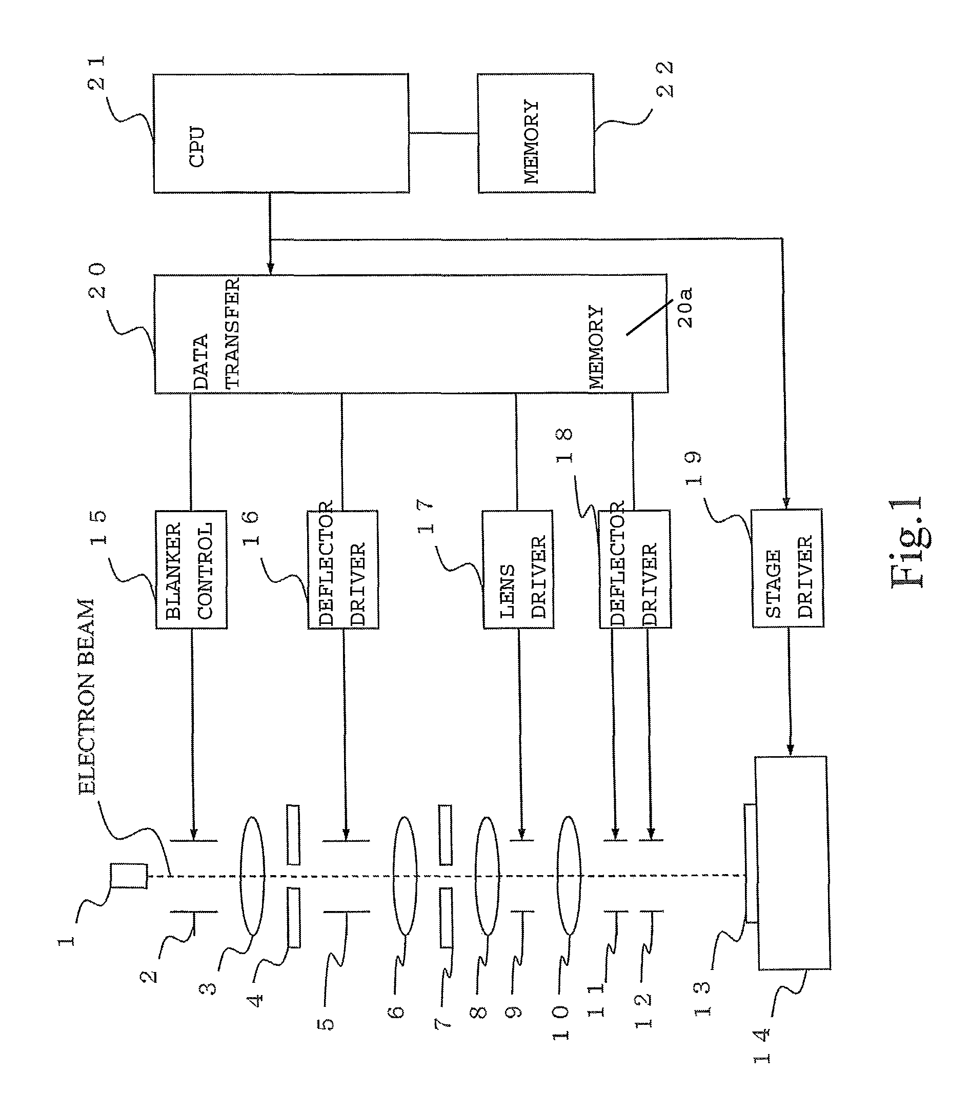
[0034]The preferred embodiments of the present invention are hereinafter described in detail. FIG. 1 schematically shows the configuration of an electron beam lithography system for implementing the method of the present invention. The system of FIG. 1 is similar in configuration with the system already described in connection with FIG. 7 except that components, including a blanker, are added. In both FIGS. 1 and 7, like components are indicated by like reference numerals.

[0035]Referring to FIG. 1, an electron gun 1 acts as a charged particle beam source that produces a beam of charged particles. The beam produced from an electron gun 1 is shot at a first shaping slit member 4 via a blanker 2 and via a shot lens 3.

[0036]The first shaping slit member 4 is provided with a rectangular aperture 4a (see also FIG. 7). The electron beam of rectangular cross section passed through the aperture is shot via a shaping lens 6 onto a second shaping slit member 7 similarly having a rectangular ap...


PUM

PropertyMeasurementUnit
diametersaaaaaaaaaa
sizeaaaaaaaaaa
diameteraaaaaaaaaa

Abstract

There is disclosed a lithography method and system implemented by a charged particle beam passed through a shaping slit member having plural circular apertures of different diameters. The method and system operate to delineate a circular pattern by shooting the shaped circular beam passed through the desired circular aperture onto a workpiece. The method and system consists of causing circular beams shaped using different ones of the circular apertures to be shot onto the workpiece such that the circular beams are coincident with each other in center position to thereby delineate a circular pattern of a desired size. Consequently, circular patterns in a wide range of sizes can be obtained, although a limited number of circular apertures are used.

Description

BACKGROUND OF THE INVENTION[0001]1. Field of the Invention[0002]The present invention relates to a method and system for charged particle beam lithography and, more particularly, to a method and system adapted for charged particle beam lithography when a circular pattern is lithographically written on a workpiece.[0003]2. Description of Related Art[0004]A variable-shaped electron beam lithography system has been developed and used as a machine that writes a fine pattern at high speed using a charged particle beam (e.g., an electron beam). In this lithography system, a variable-shaped beam of rectangular cross section is formed by the use of two shaping apertured plates each having a rectangular aperture and a shaping deflector interposed between the two apertured plates. The beam is directed at an arbitrary position on a workpiece. The workpiece is irradiated with the beam while varying the shape and area of the cross section of the beam in succession. Consequently, a microscopic pa...

Claims


Application Information

Patent Timeline
Patent Type & Authority Patents(United States)
IPC IPC(8): G03F7/20
CPCH01J37/3174G03F7/704H01J2237/31776G03F7/2059H01J37/3026Y10S430/143G03F7/20B82Y10/00B82Y40/00
Inventor KIUCHI, TAICHIHASEGAWA, TAKAHISA
Owner JEOL LTD
Why Eureka
Try Eureka