
Gas sensing system employing raman scattering

a technology of gas sensing and raman scattering, which is applied in the field of gas sensing systems, can solve the problems of no commercially available sensor or sensing system that is able, and the task of detecting and characterization of molecular gases in a given sample is a relatively difficult challeng

Active Publication Date: 2014-03-18
UNIVERSITY OF PITTSBURGH +1
View PDF13 Cites 7 Cited by
  • Summary
  • Abstract
  • Description
  • Claims
  • Application Information

AI Technical Summary

Benefits of technology

The system achieves fast and accurate measurement of gas compositions, capable of detecting multiple gases simultaneously with sub-0.1% accuracy and sampling rates of approximately one second, surpassing the capabilities of existing technologies.

Problems solved by technology

The detection and characterization of molecular gases in a given sample is a relatively difficult challenge.
Usually, this task is relegated to expensive and time consuming processes like mass spectrometry and gas chromatography.
There is currently no commercially available sensor or sensing system that is able to measure all of the natural-gas components in one second.

Method used


Image

  • Gas sensing system employing raman scattering
  • Gas sensing system employing raman scattering
  • Gas sensing system employing raman scattering

Examples


Embodiment Construction

[0029]Directional phrases used herein, such as, for example and without limitation, top, bottom, left, right, upper, lower, front, back, and derivatives thereof, relate to the orientation of the elements shown in the drawings and are not limiting upon the claims unless expressly recited therein.

[0030]As employed, herein, the statement that two or more parts or components are “coupled” together shall mean that the parts are joined or operate together either directly or through one or more intermediate parts or components.

[0031]As employed herein, the statement that two or more parts or components “engage” one another shall mean that the parts exert a force against one another either directly or through one or more intermediate parts or components.

[0032]As employed herein, the term “number” shall mean one or an integer greater than one (i.e., a plurality).

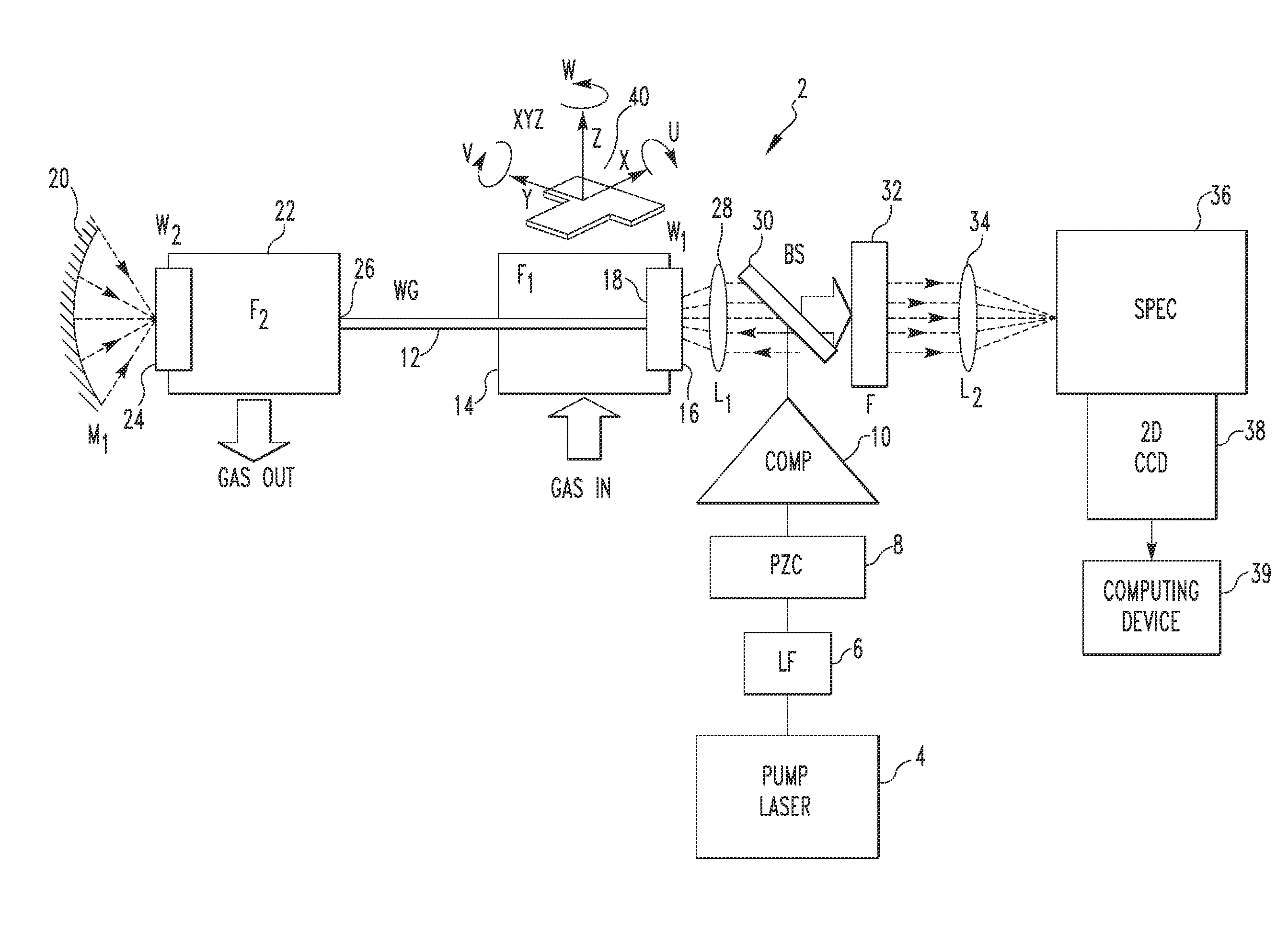
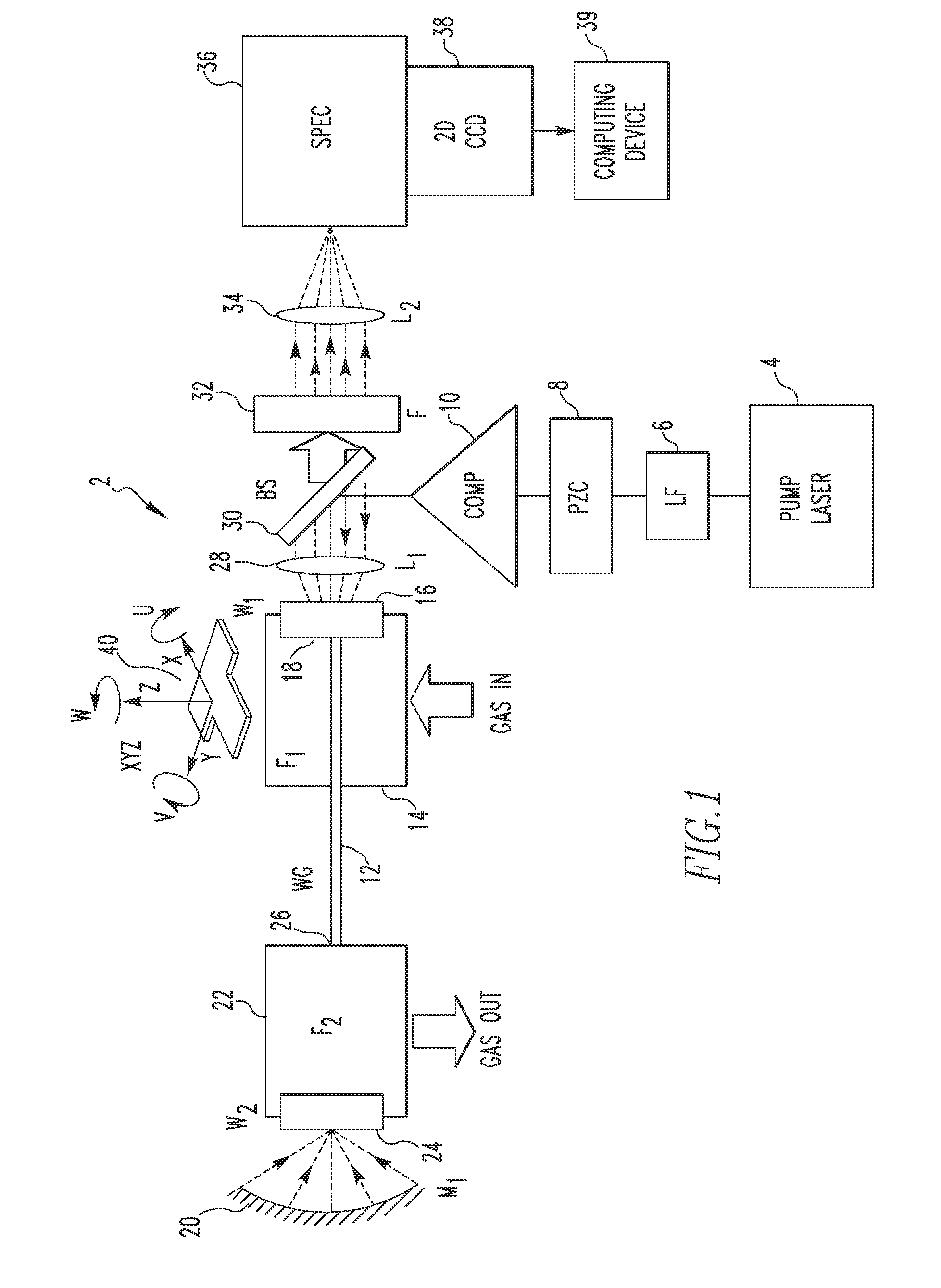
[0033]As described in greater detail herein, the present invention provides an optical Raman scattering gas detection system. As is...


PUM

PropertyMeasurementUnit
diameteraaaaaaaaaa
diametersaaaaaaaaaa
diametersaaaaaaaaaa

Abstract

A gas detection system includes a light detector, a pump laser with spectral emission between UV and IR wavelengths and structured to generate a laser beam, a hollow waveguide structured to receive a sample gas, the hollow waveguide having a bandwidth sufficient to transmit the laser beam and Stokes Raman photons scattered by the sample gas, and an optical system. The optical system is structured to: (i) direct the laser beam into the hollow waveguide such that it propagates in the hollow waveguide in one or more low-order low-loss waveguide modes, and (ii) direct Raman signals generated within the hollow waveguide in response to the laser beam interacting with the sample gas toward the light detector, the Raman signal including the Stokes Raman photons.

Description

CROSS-REFERENCE TO RELATED APPLICATIONS[0001]This application claims priority under 35 U.S.C. §119(e) from provisional U.S. patent application No. 61 / 416,936, entitled “Gas Sensing System Employing Raman Scattering” and filed on Nov. 24, 2010, the contents of which are incorporated herein by reference.GOVERNMENT CONTRACT[0002]This invention was made with government support under grant # DE-AC26-04NT41817 awarded by the DOE. The government has certain rights in the invention.BACKGROUND OF THE INVENTION[0003]1. Field of the Invention[0004]The present invention relates to gas sensing systems, and in particular, to an optical system for identifying, characterizing and / or determining the concentration of various gases in a gas mixture or sample that employs Raman scattering.[0005]2. Description of the Related Art[0006]The detection and characterization of molecular gases in a given sample is a relatively difficult challenge. Usually, this task is relegated to expensive and time consuming...

Claims


Application Information

Patent Timeline
Patent Type & Authority Patents(United States)
IPC IPC(8): G01N21/35
CPCG01N21/65
Inventor FALK, JOELCHEN, PENG KEVINBURIC, MICHAEL PAULWOODRUFF, STEVEN D.
Owner UNIVERSITY OF PITTSBURGH
Learn More