Movable body drive system and movable body drive method, pattern formation apparatus and method, exposure apparatus and method, device manufacturing method, and decision-making method

a technology of movable bodies and drive systems, applied in the direction of photomechanical devices, instruments, printing, etc., can solve the problems of inability to detect variation in measurement values (counts), inability to linearize measurement values, and inability to achieve long-term stability. , to achieve the effect of high accuracy

a technology of movable bodies and drive systems, applied in the direction of photomechanical devices, instruments, printing, etc., can solve the problems of inability to detect variation in measurement values (counts), inability to linearize measurement values, and inability to achieve long-term stability. , to achieve the effect of high accuracy

US8675171B2Inactive Publication Date: 2014-03-18NIKON CORP

Image

  • Movable body drive system and movable body drive method, pattern formation apparatus and method, exposure apparatus and method, device manufacturing method, and decision-making method
  • Movable body drive system and movable body drive method, pattern formation apparatus and method, exposure apparatus and method, device manufacturing method, and decision-making method
  • Movable body drive system and movable body drive method, pattern formation apparatus and method, exposure apparatus and method, device manufacturing method, and decision-making method

Examples


Embodiment Construction

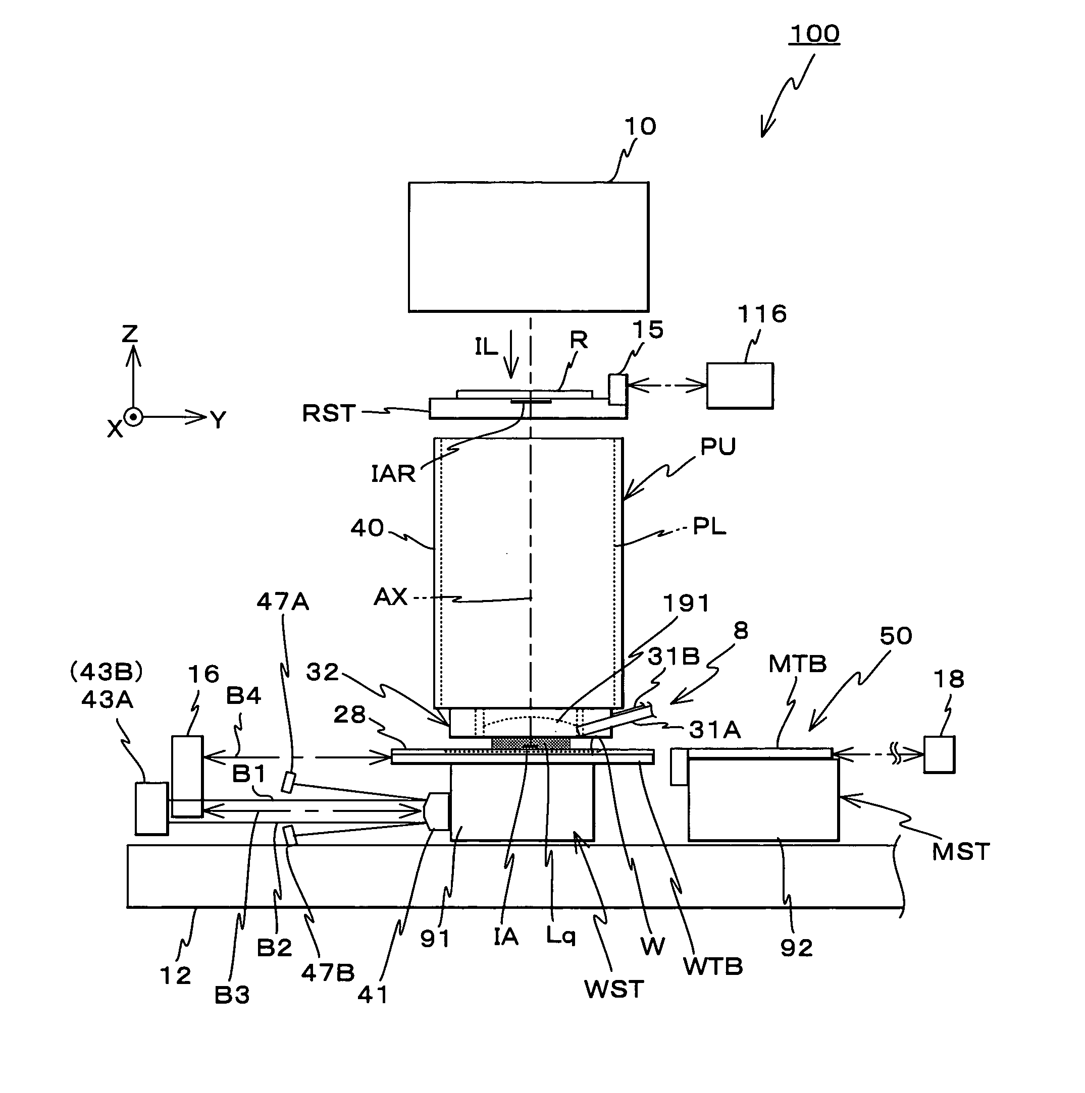
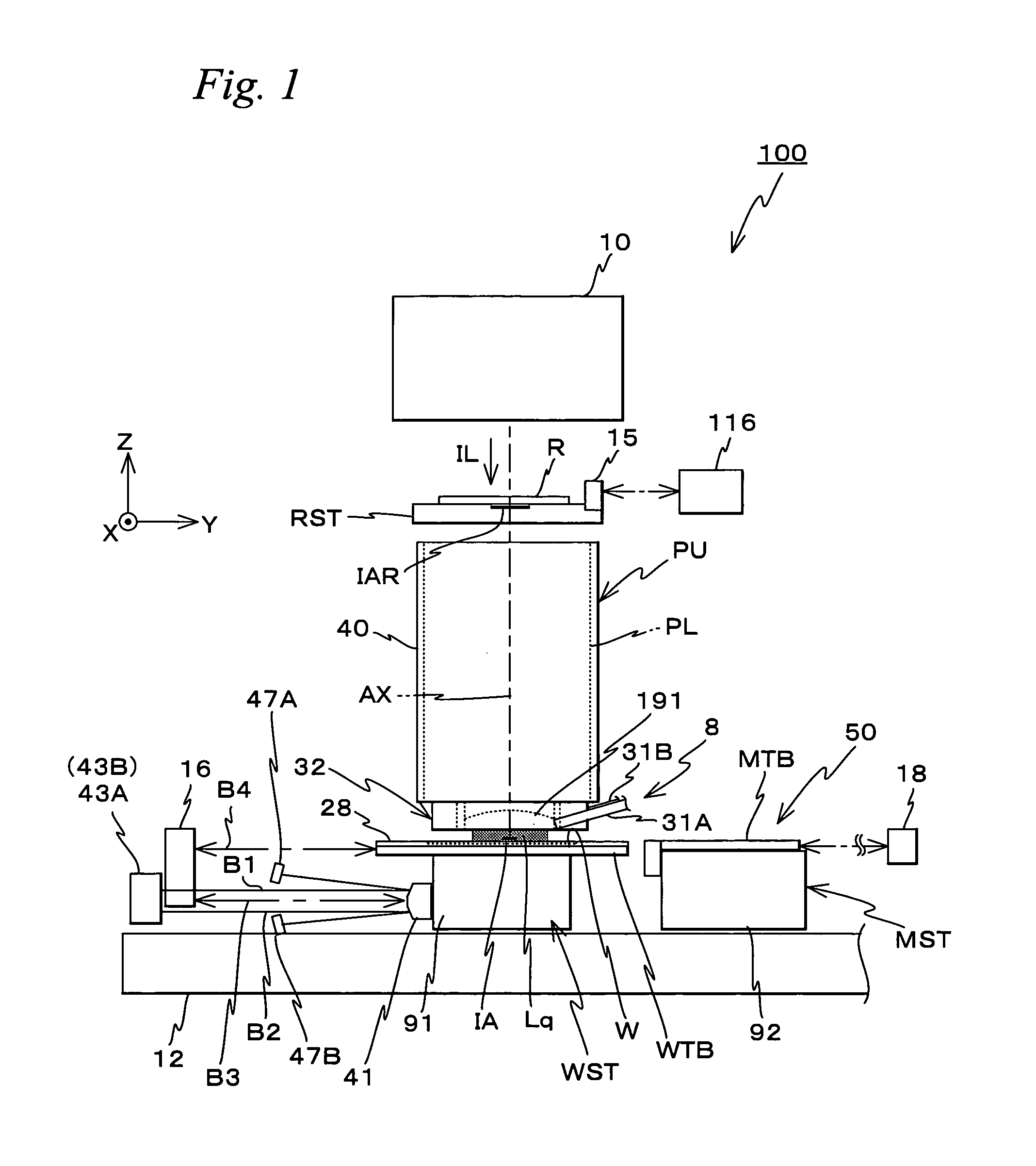
[0078]An embodiment of the present invention will be described below, with reference to FIGS. 1 to 27.

[0079]FIG. 1 schematically shows the configuration of an exposure apparatus 100 related to an embodiment. Exposure apparatus 100 is a scanning exposure apparatus by a step-and-scan method, that is, a so-called scanner. As will be described later, in the embodiment, a projection optical system PL is arranged, and the following description will be made assuming that a direction parallel to an optical axis AX of projection optical system PL is a Z-axis direction, a direction in which a reticle and a wafer are relatively scanned within a plane orthogonal to the Z-axis direction is a Y-axis direction and a direction that is orthogonal to a Z-axis and a Y-axis is an X-axis direction, and rotation (tilt) directions around the X-axis, the Y-axis and the Z-axis are ex, θy and θz directions respectively.

[0080]Exposure apparatus 100 includes an illumination system 10, a reticle stage RST that ...


PUM


Abstract

A drive unit drives a wafer table in a Y-axis direction based on a measurement value of an encoder that measures position information of the wafer table in the Y-axis direction and based on known correction information in accordance with position information of the wafer table in a non-measurement direction (e.g. Z, θz and θx directions) that is measured by an interferometer at the time of the measurement by the encoder. That is, the wafer table (a movable body) is driven in the Y-axis direction based on the measurement value of the encoder that has been corrected by correction information for correcting a measurement error of the encoder that is caused by a relative displacement of a head and a scale in the non-measurement direction. Accordingly, the movable body can be driven with high accuracy in a desired direction while measuring the position by the encoder, without being affected by the relative motion between the head and the scale in directions other than a direction to be measured (measurement direction).

Description

CROSS-REFERENCE TO RELATED APPLICATIONS[0001]This non-provisional application claims the benefit of Provisional Application No. 60 / 853,750 filed Oct. 24, 2006, the disclosure of which is hereby incorporated herein by reference in its entirety.BACKGROUND OF THE INVENTION[0002]1. Field of the Invention[0003]The present invention relates to movable body drive systems and movable body drive methods, pattern formation apparatuses and methods, exposure apparatuses and methods, device manufacturing methods, and decision-making methods, and more particularly to a movable body drive system and a movable body drive method that drive a movable body along a predetermined plane, a pattern formation apparatus equipped with the movable body drive system and a pattern formation method using the movable body drive method, an exposure apparatus equipped with the movable body drive system and an exposure method using the movable body drive method, a device manufacturing method using the pattern format...

Claims


Application Information

Patent Timeline
18 Mar 2014
Publication
US8675171B2
IPC
G03B27/42; G03B27/58; G03B27/62; G03B27/32
CPC
G03F7/70341; G03F7/70775; G03F1/44; G03F7/20; G03F7/2041; G03F7/70258; G03F7/70275; G03F7/70716
Inventors
SHIBAZAKI, YUICHI