Sensing modules and methods of using

a technology of sensing modules and sensors, applied in the field of sensing technology, can solve the problems of no current consensus of optimal monitoring parameters, no battery-free operation, and insufficient availability of environmental energy sources to power sensors, so as to improve diagnosis and treatment methods and monitor accurately

Inactive Publication Date: 2014-03-25
EVIGIA SYST
View PDF25 Cites 11 Cited by
  • Summary
  • Abstract
  • Description
  • Claims
  • Application Information

AI Technical Summary

Benefits of technology

[0012]According to preferred aspects of the invention, the sensing modules and methods are capable of very accurately monitoring impacts, shock wave pulses and other environmental parameters to which a living body may be subjected, thereby improving diagnosis and treatment methodologies. Another preferred but optional aspect is that the module is able to operate with minimal power so that power is available for module operation over longer periods of time. In particularly preferred embodiments, the electromechanical sensing elements scavenge power from the body, providing a continuous or intermittent monitoring capability over extended periods of time. The module is preferably configured to be sufficiently small and light to be attached to a body without being obtrusive, enabling the module to be used by a wide range of individuals while performing a wide variety of activities.

Problems solved by technology

Furthermore, in many applications a batteryless operation is needed due to lack of battery replacement feasibility, or to meet stringent cost, form factor, and lifetime requirements.
However, in many situations, these environmental energy sources are not adequately available to power a sensor.
Because the brain is a very complex system, there is no current consensus of optimal monitoring parameters for determining the many different types of brain injury.
However, the data from these sensors are not quickly and readily available to a field medic or other medical personnel, and do not correlate well with the actual acceleration of the head.
Furthermore, a technical complication of these systems is that the transfer function from motion of the helmet to motion of the head is different for every individual, and can depend on the fit of the helmet, tightness of the chin strap, how the helmet is worn, and many other factors that vary from individual to individual.
Though research involving animal studies have been conducted, a difficulty encountered when monitoring blast pressure waves is that most pressure sensors are directional, and it is therefore difficult to measure the shock wave pulse from a blast of unknown direction.
In addition, it is difficult to reconstruct data and then apply the data to a traumatic injury after the fact due to human reactions to the event that can affect the data (reflexes).
Consequently, the use of the shock wave pulse to diagnose and treat blast victims has been primarily limited to laboratory tests.
However, existing impact sensing systems are typically large, heavy and very expensive, consume a significant amount of power, and require batteries that must be changed on a fairly regular basis.
Aside from players of high impact sports, it is nearly impossible to predict the occurrence of head impact and the subsequent trauma.
Consequently, currently available systems are not widely used, and then typically limited to occasional uses, such as monitoring deceleration or impact on equipment worn by athletes, such as helmets of the types worn in hockey or American football.
Still, and for reasons stated previously, such uses often provide data that do not correlate well with the actual deceleration of the head.

Method used


Image

  • Sensing modules and methods of using
  • Sensing modules and methods of using
  • Sensing modules and methods of using

Examples


Embodiment Construction

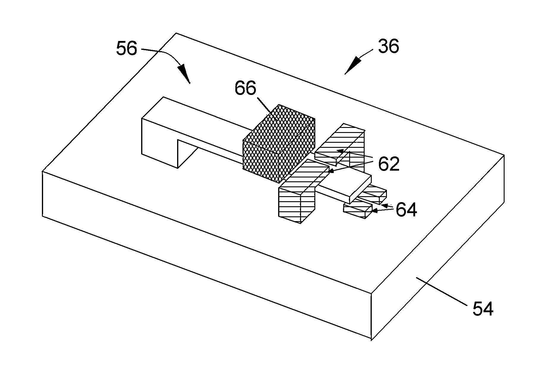
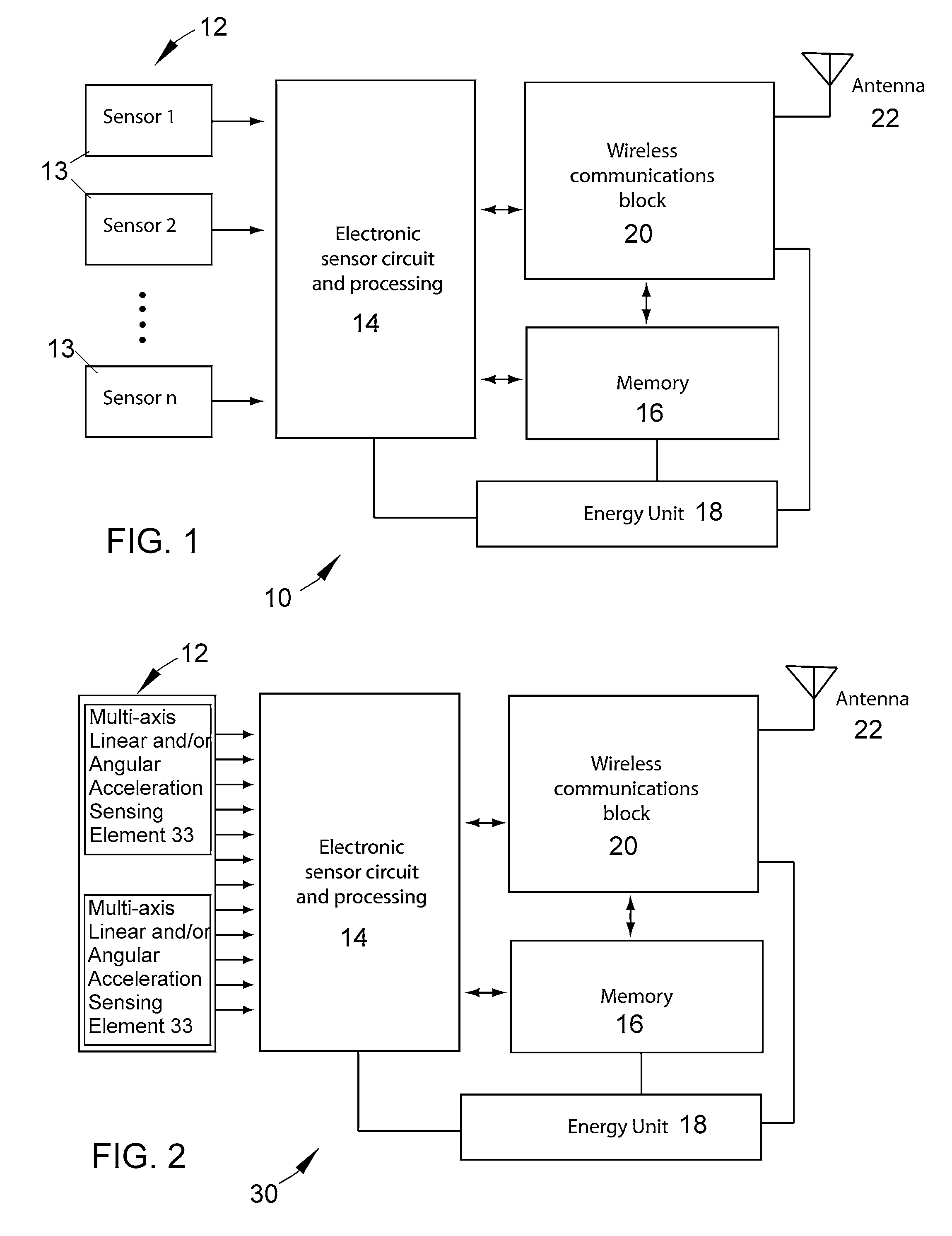
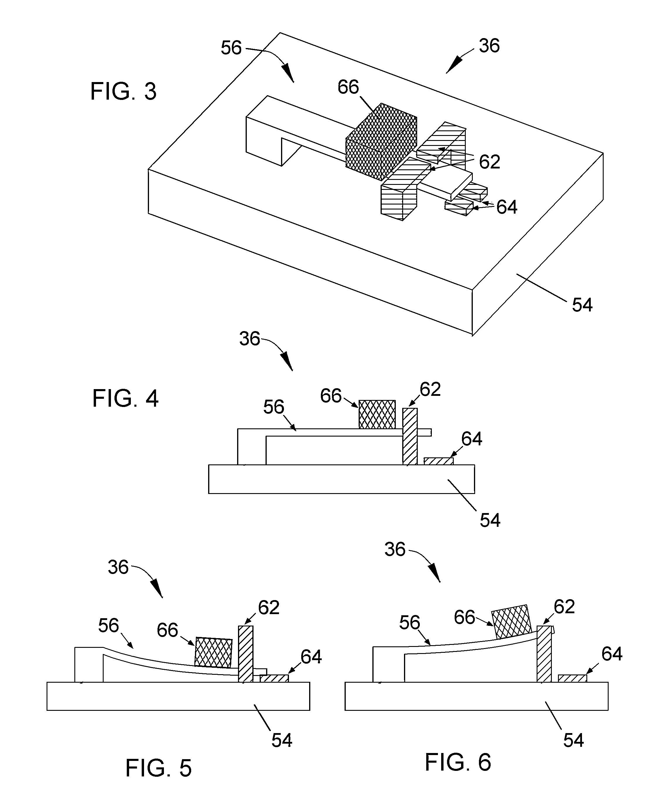
[0031]The present invention provides miniature sensing modules whose small size enables the modules to be placed on a body, including but not limited to humans or equipment or apparel worn by humans, where the modules can be used to monitor and generate data relating to one or more external inputs, such as external environmental parameters to which the body may be subjected. The modules make use of an energy storage device and at least one set of electromechanical sensing elements. The modules also preferably make use of non-volatile memory to store the data and a wireless communication system that enables the data to be retrieved from the modules by a wireless external interrogator / reader (reader) unit. The components of the modules are preferably selected so that the modules require very little power for their operation, enabling the modules to remain operable for long periods of time, potentially on the order of years, without need for replacement.

[0032]As will be evident from th...


PUM

PropertyMeasurementUnit
energyaaaaaaaaaa
energyaaaaaaaaaa
degrees of freedomaaaaaaaaaa

Abstract

A sensing module and method for monitoring various physical parameters, and particularly environmental parameters to which a living body may be subjected, for example, impacts and shock wave pulses. The module at least one energy storage device and at least one set of electromechanical sensing elements contained in a housing. The sensing elements are responsive to an external environmental input, and each sensing element defines an open electrical path when not subjected to the input, is operable to define a closed electrical path that produces an output in response to the input if the input exceeds a threshold of the sensing element. The module generates data corresponding to the outputs of the sensing elements and records the data.

Description

CROSS REFERENCE TO RELATED APPLICATIONS[0001]This application claims the benefit of U.S. Provisional Application No. 61 / 274,898, filed Aug. 24, 2009, and is a continuation-in-part patent application of co-pending U.S. patent application Ser. No. 11 / 671,130, filed Feb. 5, 2007, which claimed the benefit of U.S. Provisional Application No. 60 / 765,244, filed Feb. 4, 2006. The contents of these prior applications are incorporated herein by reference.BACKGROUND OF THE INVENTION[0002]The present invention generally relates to sensing technology that employs electromechanical sensing devices, such as micro-electromechanical systems (MEMS) and nano-electromechanical systems (NEMS). More particularly, this invention relates to sensing systems and methods capable of monitoring environmental parameters to which a body may be subjected, particular but nonlimiting examples of which are pressure and acceleration resulting from blasts and impacts sustained by a body, including a living body.[0003]...

Claims


Application Information

Patent Timeline
Patent Type & Authority Patents(United States)
IPC IPC(8): G01P15/00G01N3/30G01M7/00G01N3/32
CPCH01H2300/032Y02B90/224G01P15/0888G01K5/62H01H2203/0085H01H35/24Y04S20/14H01H69/01H01H35/42H01H2001/0063G01P15/135H01H2037/008G01D21/00H01H35/14H01H1/0036G01P15/18G01P2015/0828Y02B90/20
Inventor HOWER, ROBERT WILLIAMZHANG, YAFANYAZDI, NAVID
Owner EVIGIA SYST
Why Eureka
Try Eureka