Switchable lever for a valve drive of an internal combustion engine

a technology of internal combustion engine and switchable lever, which is applied in the direction of engine components, machines/engines, mechanical apparatus, etc., can solve the problems of complex actuation of the axle, and achieve the effect of reducing the effort expended on actuation

Inactive Publication Date: 2014-03-25
SCHAEFFLER TECH AG & CO KG
View PDF15 Cites 34 Cited by
  • Summary
  • Abstract
  • Description
  • Claims
  • Application Information

AI Technical Summary

Benefits of technology

[0007]A lever is therefore present without the disadvantages referred to at the beginning. A particularly outstanding feature of the invention is the ultimately telescopic nesting of the three cam rollers, thus making it possible to save on construction space laterally. At the same time, forces are introduced into the lever symmetrically during the cam lift such that the lever has only an insignificant tilting tendency, if any at all. The cam rollers, in particular the high-lift cam rollers, can be physically relatively broad such that the loading on the components by the surface pressure is minimized. In addition, simple internal actuating means are proposed for the cam rollers for the displacement thereof (hydraulic medium / compression spring), and separate pressure spaces for the hydraulic medium can be omitted, as can separate coupling means, owing to the pressure spaces being formed axially between the cam rollers. It is obvious that this simultaneously provides excellent lubrication of the sealing rotary tapping between the inner annular casing of the low-lift cam roller and a diameter step, which runs therein, of the respective high-lift cam roller.
[0010]At least one co-rotating helical compression spring clamped indirectly between the high-lift cam roller and the side wall of the lever is proposed per high-lift cam roller as the spring means (second servo means) for producing the second, retracted position, with other types of springs, such as disk springs, etc., also being possible. The respective helical compression spring expediently sits in an annular pocket of an outer face of the high-lift cam roller, thus saving construction space.
[0011]It is advantageous here to place the corresponding annular pocket to be radially lower than the inner diameter step of the high-lift cam roller, such that there is sufficient construction depth.
[0013]Axially on the inside, the abovementioned pipe section, which is composed, for example, of sheet metal, has simple, crown-like apertures, thus permitting an unobstructed overflow of the hydraulic medium out of the axle into the respective pressure space.
[0017]Owing to the optionally provided support surfaces, for example on upper sides of the side walls, the lever can be supported as it passes through the cam base circle such that the respective cam base circles are free from contact with the cam rollers, which minimizes the effort expended on displacing the latter. Possible mating support surfaces include, for example, support cams on the cam shaft or elements which protrude from the cylinder head and project beyond the side walls.

Problems solved by technology

It is noticeable that the axle has to be acted upon in a complicated manner via external means in order to be displaced.

Method used


Image

  • Switchable lever for a valve drive of an internal combustion engine
  • Switchable lever for a valve drive of an internal combustion engine
  • Switchable lever for a valve drive of an internal combustion engine

Examples


Embodiment Construction

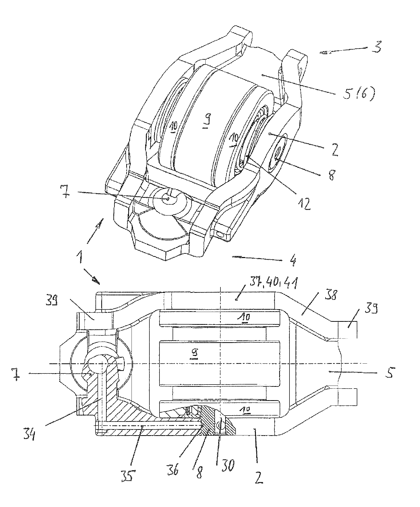
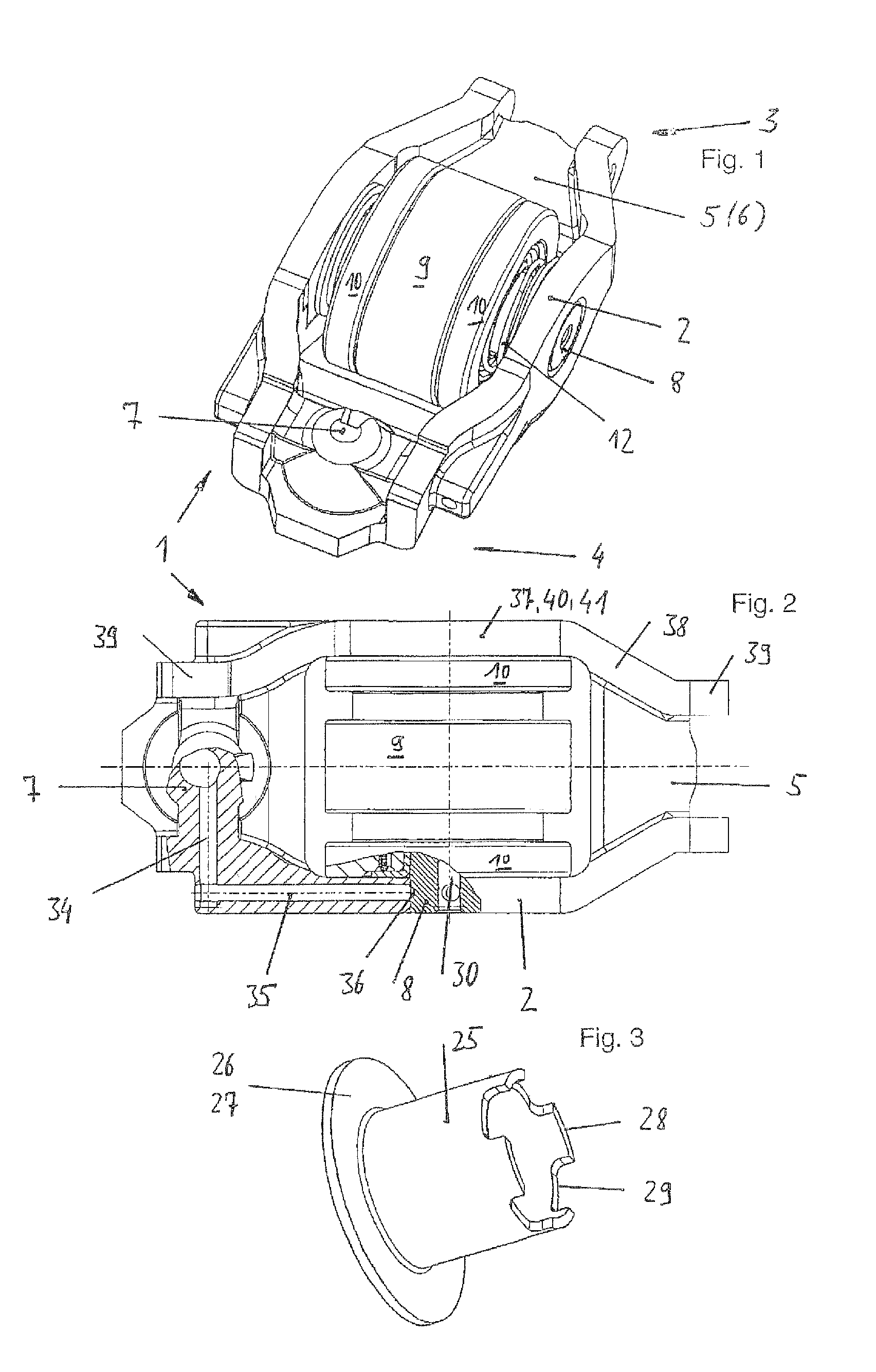
[0024]A switchable lever 1 in the form of a rocker arm lever for a valve drive of an internal combustion engine is illustrated. Said lever has a box-shaped geometry in top view and consists of two upright side walls 2, the ends 3, 4 of which are connected on their lower side by a cross bar 5. The side walls 2 have an expanded center section 37, which expanded center section 37 is adjoined by intermediate sections 38 which face each other and peter out in rectilinear end sections 39.

[0025]There is a gas-exchange valve system 6 in the crossbar 5 at the one end 3 and a bearing 7, which is designed as a dome-shaped formation and is intended for the pivotable supporting of the lever 1, at the other end 4. An axle 8 is held nondisplaceably in the side walls 2 between the ends 3, 4. Two axially displaceable high-lift cam rollers 10, which enclose a low-lift cam roller 9, run on said axle.
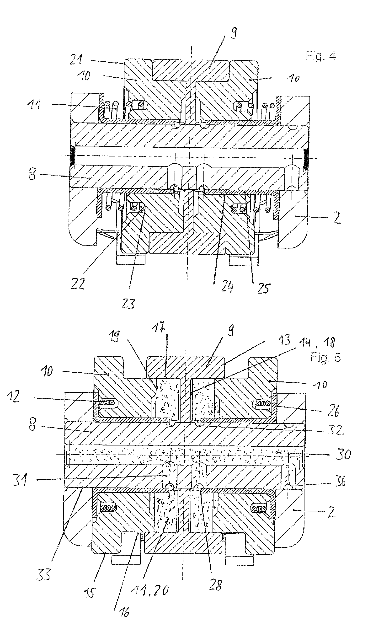
FIGS. 4, 5:

[0026]The low-lift cam roller 9 has a cylindrical pocket 14 on both end sides 13, and each h...


PUM


Abstract

A switchable lever for a valve drive of an internal combustion engine, which has an elongated housing with two side walls. A crossbar for a gas-exchange valve system and another end of the housing has a hearing for pivotable support of the crossbar. An axle is held nondisplaceably in the side walls. An axially fixed low-lift cam roller is seated centrally on the axle and is flanked on both sides by a high-lift cam roller. The high-lift cam rollers are displaceable: (a) into a first position, away from each other, to toward the side walls such that contact of one high-lift cam per high-lift cam roller is possible, and (b) into a second position, toward each other, such that they are located outside an engagement region of the high-lift cams, and as a result of which contact of a low-lift or zero-lift cam with the low-lift cam roller is possible.

Description

CROSS-REFERENCE TO RELATED APPLICATION[0001]This application claims the priority of DE 10 2010 019 064.0 filed May 3, 2010, which is incorporated by reference herein.FIELD OF THE INVENTION[0002]The invention relates to a switchable lever for a valve drive of an internal combustion engine.BACKGROUND OF THE INVENTION[0003]The lever revealed in subsequently published DE 102010011828.1 is considered to be the closest prior art. It is noticeable that the axle has to be acted upon in a complicated manner via external means in order to be displaced. In association therewith, the abovementioned lever requires a relatively large amount of construction space laterally, and, at least in the switching state shown in FIG. 5, an asymmetrical introduction of force occurs during the cam lift. It is also ascertained that the central region of the lever has a relatively large bulge because of the displaceable cam rollers positioned next to one another on the axle.[0004]It is therefore the object of t...

Claims


Application Information

Patent Timeline
Patent Type & Authority Patents(United States)
IPC IPC(8): F01L1/34F01L1/18
CPCF01L1/185F01L13/0005F01L2103/00F01L13/0036F01L2105/00F01L2303/00F01L2305/00
Inventor BECKER, MATTHIASHEINEMANN, ROBERT
Owner SCHAEFFLER TECH AG & CO KG
Why Eureka
Try Eureka