
Wearable rebreathing apparatus

a rebreathing apparatus and wearable technology, applied in the field of closed circuit rebreathing, can solve the problems of scrubbing canisters being cumbersome to wear, affecting the overall weight distribution of wearers, so as to achieve maximum velocity, minimize drag, and high hydrodynamics

Active Publication Date: 2014-03-25
BREATHEATOR VEST SYST
View PDF5 Cites 4 Cited by
  • Summary
  • Abstract
  • Description
  • Claims
  • Application Information

AI Technical Summary

Benefits of technology

The rebreather vest enhances hydrodynamics, reduces fatigue, and maintains performance by evenly distributing weight and reducing respiration pressure, allowing for efficient and maneuverable use both underwater and on land.

Problems solved by technology

While extremely useful, current rebreathers suffer from certain limitations.
The large mounted scrubbing canister is cumbersome to wear and throws the overall weight distribution of the wearer far off from ideal.
A land-based user finds such large canisters and the uneven weight distribution occasioned by the canisters to impede maneuverability and increase overall fatigue.
Water-based users find that the canisters change the natural contours of the body so as to make the user less hydrodynamic via increased drag which decreases swimming speed and also increases fatigue.
If the underwater user is scooter-based, the increased profile provided by current rebreathers increases overall drag which decreases scooter performance and decreases battery life.
If a water-based user transitions to land, the uneven weight loading provided by the rebreather makes the transition awkward at best.
Additionally, the diver is subject to hydrostatic loads due to the extra force required to breathe into a counter-lung above or exhale into a volume below the diver's chest.

Method used


Image

  • Wearable rebreathing apparatus
  • Wearable rebreathing apparatus
  • Wearable rebreathing apparatus

Examples


Embodiment Construction

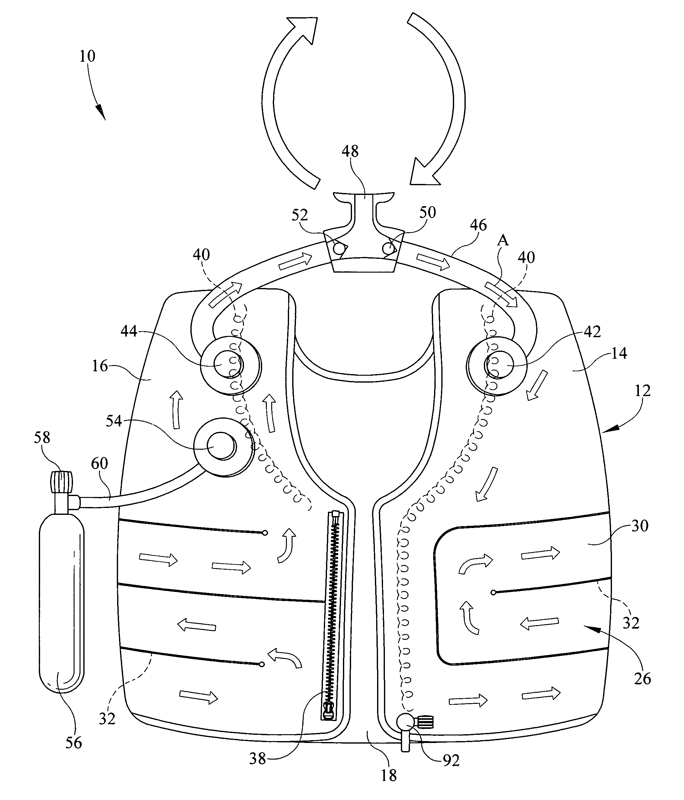
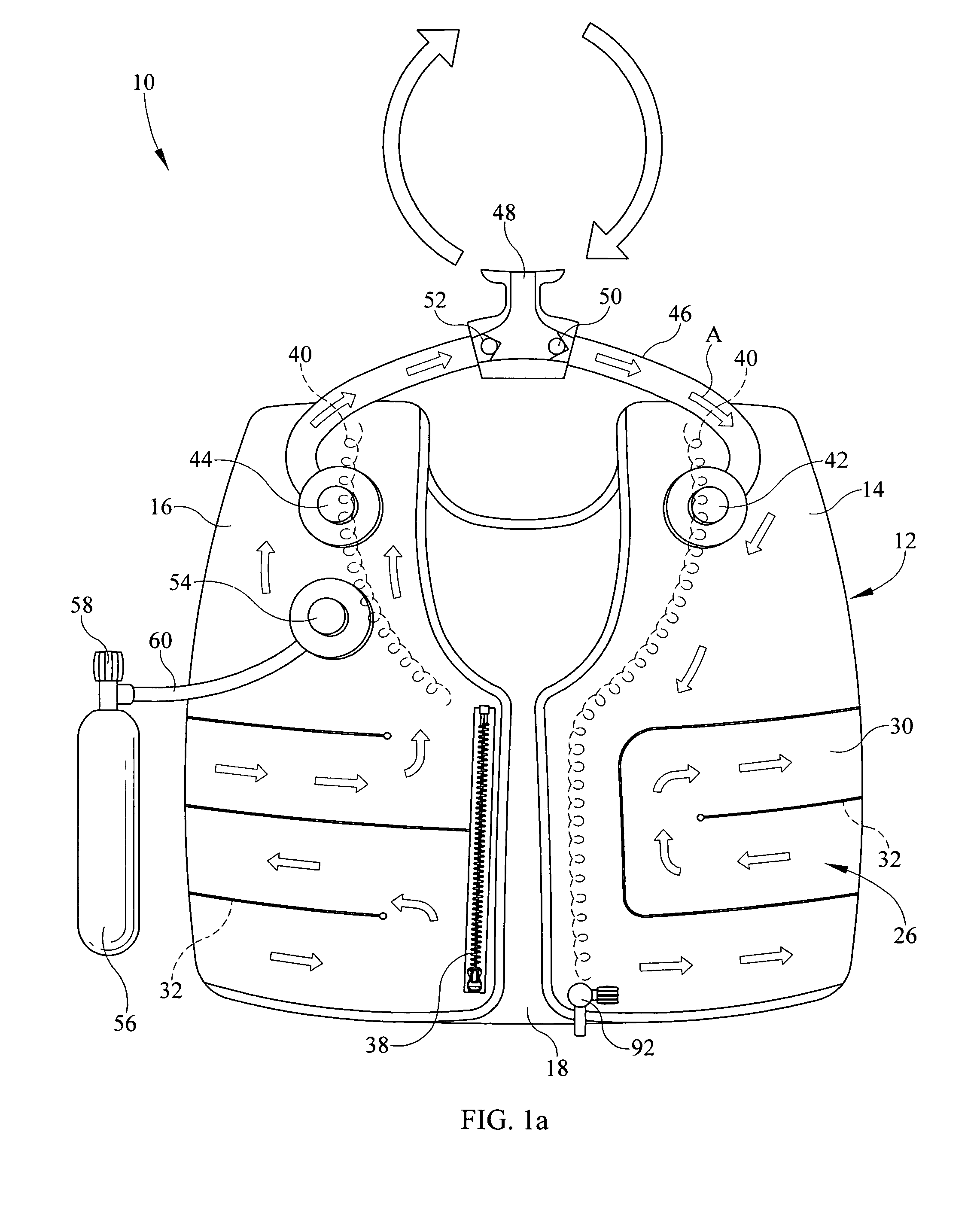
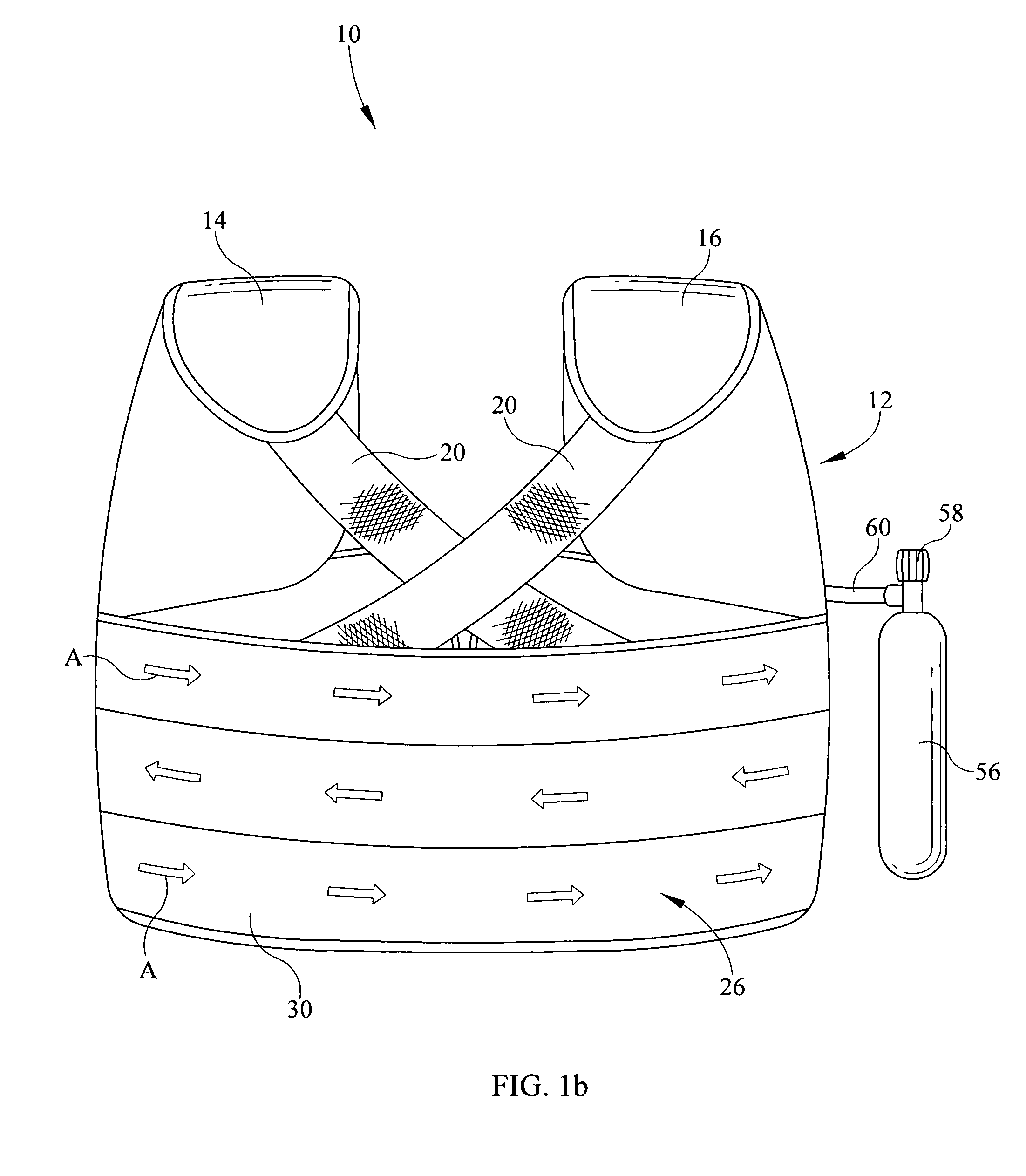
[0020]Referring now to the drawings, it is seen that the rebreather vest of the present invention, generally denoted by reference numeral 10, is comprised of a vest 12 of typical human torso configured vest configuration having a front left portion 14 that serves as a first counter-lung, a front right portion 16 that serves as a second counter-lung joined by a back portion 18. Webbing 20 may be used to join the back portion 18 with the ends of the front portions 14 and 16 or the back portion 18 may be full. Appropriate closure mechanisms (zipper, snap, latches, etc.,—none illustrated)—can be used to close the front of the vest 12 in the usual way.

[0021]In the embodiment illustrated in FIG. 1a, the vest 10 has a first front closure edge, right closure edge or right closure segment extending substantially parallel to, and adjacent to, the zipper at opening 38. Likewise, the vest 10 has a second front closure edge, left closure edge or left closure segment shown, in FIG. 1a, opposite o...


PUM


Abstract

A rebreathing apparatus has a clothing article wearable on a person. The clothing article defines a channel configured to be fluidly connected to at least one tube. The tube is configured to be fluidly connected to a mouthpiece. When the person exhales, the exhaled breath enters one end of the channel and passes through the channel while being scrubbed of CO2. When the user inhales, the scrubbed air is drawn from the channel.

Description

BACKGROUND OF THE INVENTION[0001]1. Field of the Invention[0002]The present invention related to a closed circuit rebreather wherein the carbon dioxide (CO2) scrubbing material is imbedded within a body worn vest in order to minimize the profile of the rebreather as well as to use the natural breathing rhythm of the user to assist in the function of the rebreather.[0003]2. Background of the Prior Art[0004]Rebreathers are used in a wide variety of applications including military settings, especially underwater teams that desire to remain stealth and not have air bubbles surface as would be the case if using open circuit breathing apparatus. Other applications include mine rescue or other industries where poisonous gas may be present or oxygen absent, manned space vehicles and space suits where a person is effectively in a vacuum, hospital anesthesia breathing systems that supply appropriately proportioned gas mixtures to a patient without letting the gas escape to be breathed by hosp...

Claims


Application Information

Patent Timeline
Patent Type & Authority Patents(United States)
IPC IPC(8): A62B23/02A62B7/10A62B9/00A62B7/00
CPCA62B7/10A62B7/08
Inventor COWGILL, DAVID, E.
Owner BREATHEATOR VEST SYST
Learn More