Sound monitoring system for sound field selection based on stored microphone data
a microphone data and sound monitoring technology, applied in the field of sound monitoring and speech collection technology, can solve the problems of degrading monitoring accuracy and noise, and achieve the effects of improving work efficiency, high accuracy extracting acoustic changes, and efficient processing of sound information
- Summary
- Abstract
- Description
- Claims
- Application Information
AI Technical Summary
Benefits of technology
Problems solved by technology
Method used
Image
Examples
first embodiment
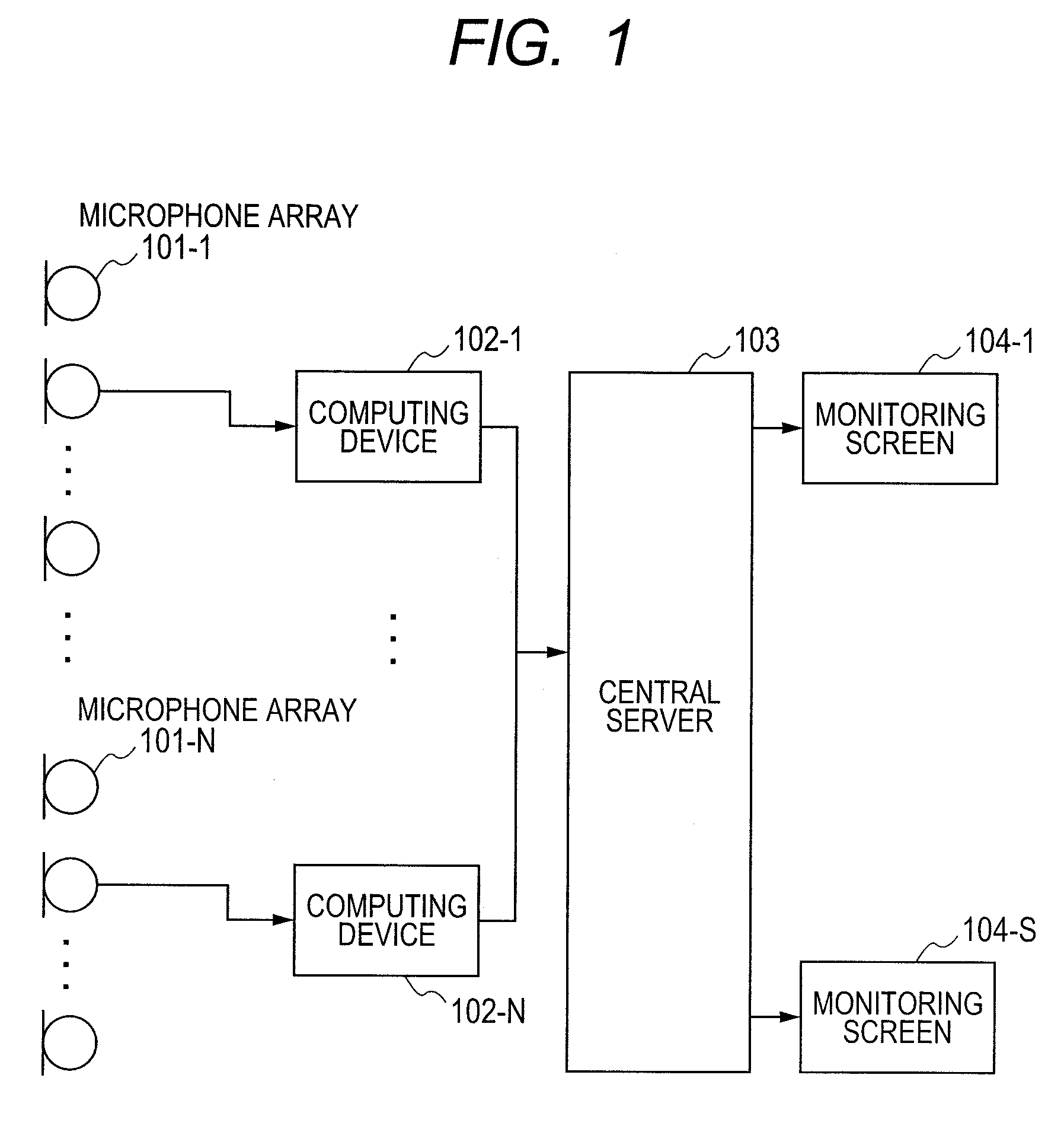
[0036]FIG. 1 shows an overall configuration of a maintenance and monitoring system according to the first embodiment. An input section includes microphone arrays 101-1 through 101-N having N microphone elements embedded in an environment such as a factory. The input section is supplied with an input signal used as sound information. Computing devices 102-1 through 102-N as signal processing sections apply digital signal processing to the sound information and extract abnormality information. The extracted abnormality information is transmitted to a central server 103. The central server 103 synthetically processes (abnormality information extraction) the abnormality information extracted by the microphone arrays 101-1 through 101-N and then transmits the information to monitoring screens 104-1 through 104-S (S is equivalent to the number of monitoring screens) as display sections viewed by operators. The microphone arrays 101-1 through 101-N at locations acquire analog sound pressur...
second embodiment
[0114]The second embodiment relates to a video conferencing system that uses the sound source orientation detection block and multiple display devices.
[0115]FIG. 22 shows a hardware configuration of the video conferencing system according to the embodiment. A microphone array 2201 including multiple microphones is installed at each conferencing location. The microphone array 2201 receives a speech signal. A multichannel A / D converter 2202 converts the analog speech signal into a digital signal. The converted digital signal is transmitted to a central processing unit 2203. The central processing unit 2203 extracts only an utterer's speech at the conferencing location from the digital signal. A speaker 2209 reproduces a speech waveform transmitted as a digital signal from a remote conferencing location via a network 2208. The microphone array 2201 receives the reproduced sound. When extracting only an utterer's speech, the central processing unit 2203 removes a sound component reprodu...
third embodiment
[0120]FIG. 21 relates to the third embodiment and exemplifies a software block configuration of applying the sound source orientation detection block to a sound recording apparatus or a speech collection system. A sound source orientation detection block 2101 detects the sound source orientation as shown in FIG. 18. A block of sound-source-oriented microphone array identification 2102 finds a microphone array toward which the sound source is oriented. A recording apparatus (not shown) records the speech collected by the identified microphone array in a block of recording a signal of the identified microphone 2103. Such configuration enables recording using the microphone array toward which the utterer faces. The speech can be recorded more clearly.
[0121]The present invention is useful as a sound monitoring technology or a speech collection technology for acoustically detecting an abnormal apparatus operation in an environment such as a factory where multiple apparatuses operate.
PUM
 Abstract
Description
Claims
Application Information
 - R&D
- Intellectual Property
- Life Sciences
- Materials
- Tech Scout
- Unparalleled Data Quality
- Higher Quality Content
- 60% Fewer Hallucinations
Browse by: Latest US Patents, China's latest patents, Technical Efficacy Thesaurus, Application Domain, Technology Topic, Popular Technical Reports.
© 2025 PatSnap. All rights reserved.Legal|Privacy policy|Modern Slavery Act Transparency Statement|Sitemap|About US| Contact US: help@patsnap.com


