Belted gear assembly for driving a supercharger

a supercharger and gear assembly technology, applied in the direction of gearing, machines/engines, electric control, etc., can solve the problem of unusability of motor vehicles, and achieve the effect of improving system efficiency and enhancing supercharger performan

Inactive Publication Date: 2014-04-01
THOMSON STEPHEN J
View PDF14 Cites 0 Cited by
  • Summary
  • Abstract
  • Description
  • Claims
  • Application Information

AI Technical Summary

Benefits of technology

[0009]In an illustrative embodiment, the belt drive assembly for the gear drive assembly is readily adjustable by merely changing the lower pulley that is operatively connected to the crank shaft. Changing the lower pulley advantageously, and relatively easily, allows modification of the amount of boost delivered by the supercharger by altering the speed at which the bevel gears rotate. A motor need not be modified to change the amount of boost, but rather a quick pulley change can be performed. This advantageously reduces the cost of maintenance and modifications, and significantly reduces the amount of time required to perform the maintenance.
[0012]An auxiliary fuel system can be provided to further enhance performance of the supercharger by ensuring adequate fuel is provided to the engine at the outlet of the supercharger. This forces sufficient gas to the engine intake along with the boost output from the supercharger. The auxiliary fuel system incorporates a manifold absolute pressure (MAP) sensor that reads the pressure at the outlet of the supercharger to determine the amount of boost being driven into the engine intake. This determines the amount of fuel to be provided by an auxiliary fuel injector to the engine intake at the outlet of the supercharger. Accordingly, the precise amount of fuel delivered to the engine intake can be fine-tuned based upon the precise amount of boost being output by the supercharger. This further improves the efficiency of the system

Problems solved by technology

Thus, any damage to the supercharger or drive assembly will not result in the motorcycle being unusable, as the motor will still function properly.

Method used


Image

  • Belted gear assembly for driving a supercharger
  • Belted gear assembly for driving a supercharger
  • Belted gear assembly for driving a supercharger

Examples


Embodiment Construction

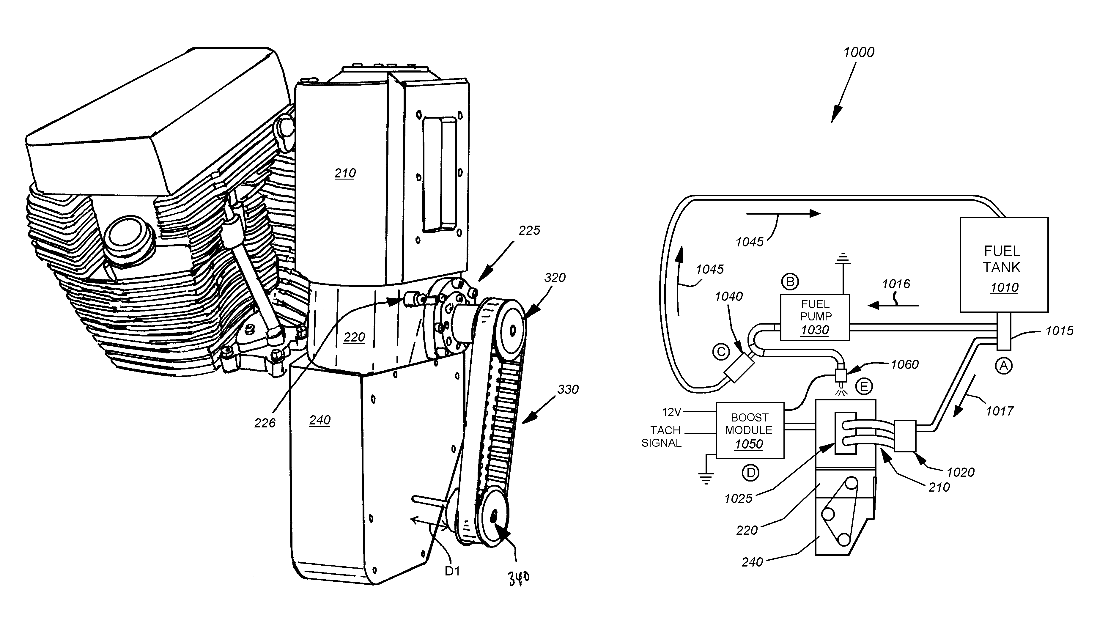
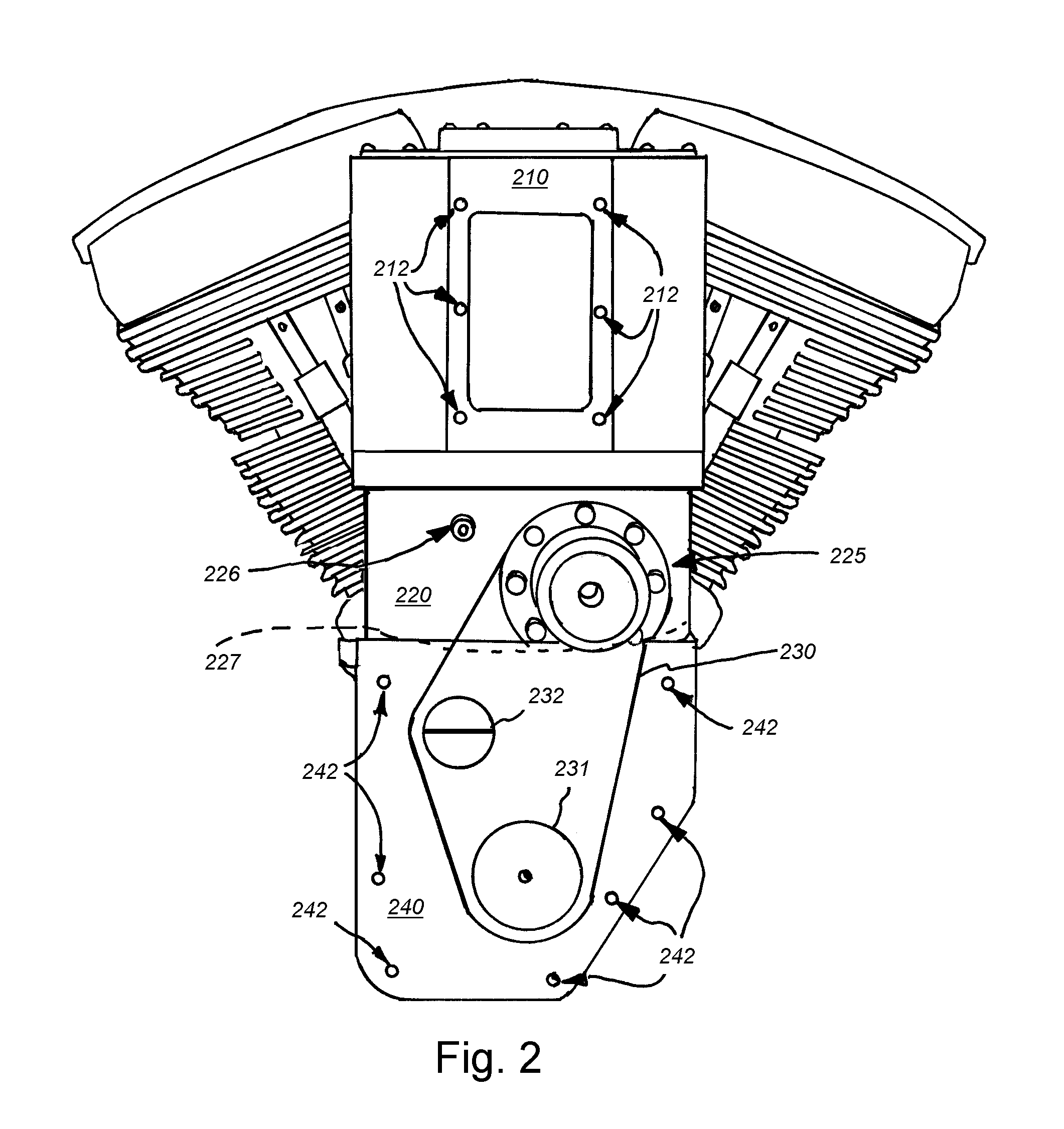
[0026]A belted gear assembly for driving a supercharger improves the performance of an internal combustion engine, and furthermore provides an adjustable and fully self-contained housing for driving a vertically aligned supercharger. It is noted that as used herein, the term “gear drive assembly” and its housing refers to the elements and associated interconnections between the supercharger and a pair of gears disposed within the gear drive housing. The gear drive assembly comprises the elements and components for driving the supercharger from an upper (or side) external pulley operatively connected to one gear in communication with a side gear in communication with the gear of the supercharger. The term “belted drive assembly” refers to the elements and associated interconnections for the belted connection between the pinion shaft (or other appropriate interconnection such as an engine's cam shaft) of the motor and the gear drive assembly. The belted drive assembly includes the ext...


PUM


Abstract

A belted gear assembly for driving a supercharger includes a belt drive assembly for operatively connecting a gear drive assembly to an existing pinion shaft of an engine. The belt drive assembly includes a lower pulley assembly that is operatively connected to the pinion shaft and belted to an upper pulley assembly. The upper pulley assembly is operatively connected to a side gear of the gear drive assembly. The side gear engages an upper gear of the gear drive assembly, which is operatively connected to a lobe of the supercharger. Rotation of the upper gear thereby initiates rotation of the supercharger. The amount of boost provided to the supercharger is readily adjustable by simply changing the lower pulley assembly to adjust the RPM ratio for the supercharger. Each component of the belted gear assembly is isolated and fully self-contained, including a separate lubrication system and collection well.

Description

RELATED APPLICATIONS[0001]This application claims the benefit of U.S. Provisional Application Ser. No. 61 / 354,511, filed Jun. 14, 2010, entitled BELTED GEAR ASSEMBLY FOR DRIVING A SUPERCHARGER, the entire disclosure of which is herein incorporated by reference.FIELD OF THE INVENTION[0002]The present invention relates to an assembly for driving a supercharger, and related systems and methods.BACKGROUND OF THE INVENTION[0003]For a two-cycle or four-cycle internal combustion engine, in operation, air is introduced to the fuel for proper combustion. A motorcycle, snowmobile, or other motorized vehicle having a fuel injection or carburetion system, includes appropriate ducting to introduce air into the fuel to create an adequate air / fuel mixture for combustion. A conventional motorcycle, as shown in FIG. 1, includes an air breather 110 which provides air for the fuel combustion. The air breather 110 provides the sole intake of air into the fuel system of the engine. Note a cover plate 12...

Claims


Application Information

Patent Timeline
Patent Type & Authority Patents(United States)
IPC IPC(8): F01D25/18F02B39/04F02D41/34F02B39/14F02D23/02F02B33/38F02D41/00F02B33/00F01M1/00F16H57/02
CPCF02D2200/0406F02B39/14F02D41/0007F02D41/34F02B33/38F02B39/04F02D2400/11Y10T74/2188Y10T74/19665
Inventor THOMSON, STEPHEN, J.
Owner THOMSON STEPHEN J
Why Eureka
Try Eureka