Step stool

a step stool and step technology, applied in the field of step stool, can solve problems such as inconvenient use, and achieve the effect of difficult us

Active Publication Date: 2014-04-01
NEW TEC INTEGRATION (XIAMEN) CO LTD
View PDF32 Cites 18 Cited by
  • Summary
  • Abstract
  • Description
  • Claims
  • Application Information

AI Technical Summary

Benefits of technology

[0025]Compared to the existing technology, the present invention has the following advantages:
[0032]Two lock pins are disposed along the front leg tubes for connecting the bottom footplate with enhanced strength, and preventing rotation of the bottom footplate. The footplate includes a supporting frame, which provides an effective means for connecting an exterior component. The lock pin is a rivet, which is convenient for assembly. The plastic element is conical frustum shaped with the base touching the footplate and the cap touching the leg tubes, which is convenient for the footplate rotation with reduced friction. At the same time, with the plastic element disposed between the leg tubes and the footplate, the footplate can be designed to new antiskid structure, which makes the step stool easily for use and highly reliable.

Problems solved by technology

As can be seen from the above, the release includes several steps with complicated release, resulting in inconvenient use.

Method used


Image

  • Step stool
  • Step stool
  • Step stool

Examples


Embodiment Construction

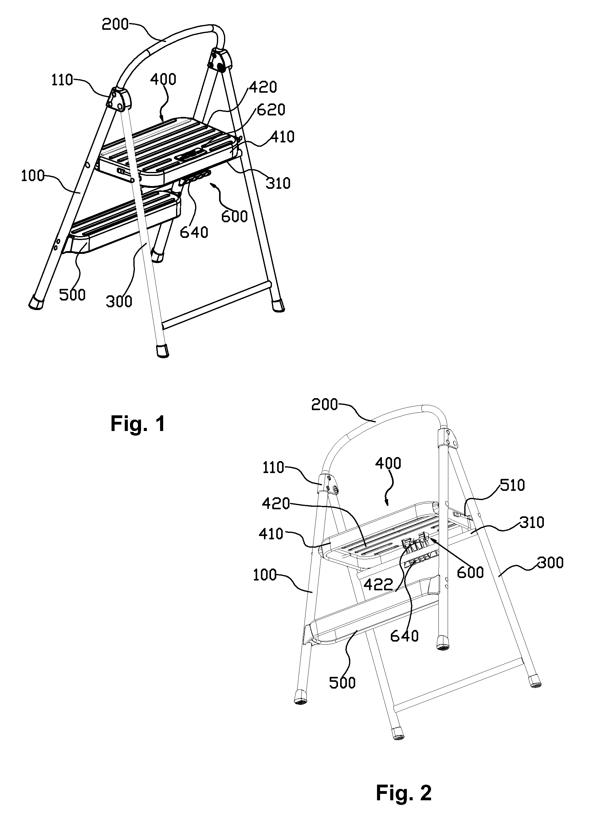
[0049]Referring to FIGS. 1 and 2, the step stool includes two front leg tubes 100, a U-shaped tube 200, two rear leg tubes 300, a top footplate 400, a bottom footplate 500 disposed between the two front leg tubes 100 and a latch device 600.

[0050]The end of the U-shaped tube 200 fixes to the top of the front leg tube 100 by a connecting member 110, the top of the rear leg tubes 300 pivotally join the connecting member 110, so that the front leg tubes 100 rotatably connect to the rear leg tubes. A rail 310 is disposed between the two rear leg tubes 300.

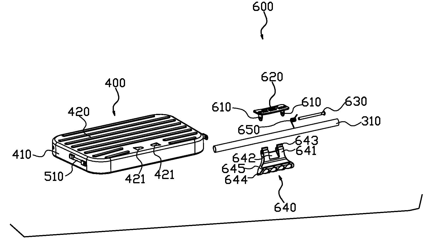
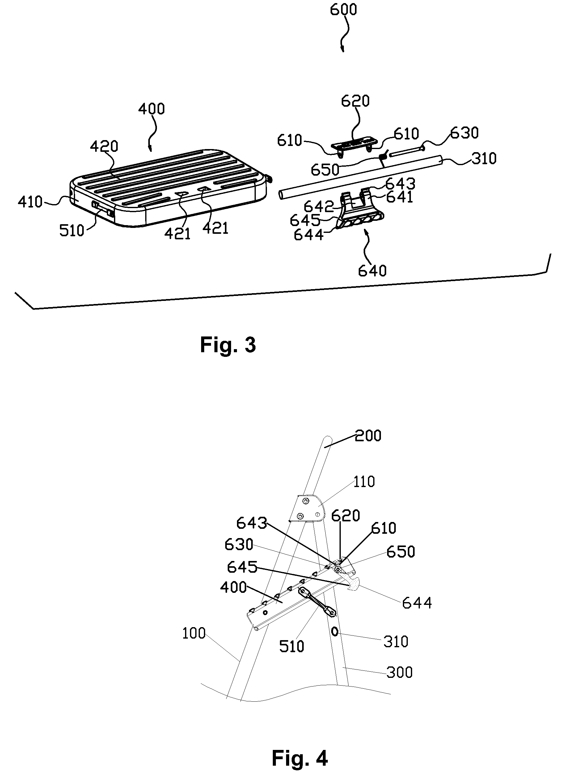
[0051]Referring to FIGS. 1 to 3, the top footplate 400 is stamped integrally by a steel piece or a thin aluminum plate (or injection molded by injection plastic in one step molding). The top footplate 400 includes a rectangle supporting frame 410 and a panel 420 fixed on the supporting frame 410. The front end of the supporting frame 410 pivotally join the two front leg tubes 100. A pivot piece 510 is disposed in the top footplate 400. ...


PUM


Abstract

A step tool has front and rear leg tubes, a bottom and top footplate, a connection device for connecting the footplate and the leg tubes, a lock catch device of the top footplate. The front leg tubes are joined to the rear leg tubes rotatablely. The foreside of the top footplate joins to the front leg tubes rotatablely. A rail is fixed on the rear leg tubes. The lock catch is disposed on the top footplate and is detachly connected to the rail. The lock catch device includes two connecting ears, a rotation axis, a lock catch and a torsion spring.

Description

FIELD OF THE INVENTION[0001]The present invention relates to a step stool.BACKGROUND OF THE INVENTION[0002]The existing step stool includes front leg tubes, rear leg tubes, a top footplate and a latch device. The front leg tubes pivotally join the rear leg tubes. The front portion of the top footplate pivotally joins the front leg tubes. A rail is provided between the rear leg tubes. The latch device is disposed in the top footplate and joins the rail, the leg tubes and a footplate disposed between the two leg tubes for assembly and disassembly. The step stool is used as a special ladder for a user to work on positions high above ground, the top footplate requires a solid connection to the other parts of the step stool. One such prior art step stool is described in the published patent application CN2889017Y entitled “A Latch Structure of the Step Stool” on Apr. 18, 2007 in the Chinese patent database in which a latch structure of the step stool is described. The latch structure inc...

Claims


Application Information

Patent Timeline
Patent Type & Authority Patents(United States)
IPC IPC(8): E06C1/387E06C1/20
CPCE06C1/393E06C1/387E06C7/083E06C1/20A47C12/00
Inventor LENG, LUHAO
Owner NEW TEC INTEGRATION (XIAMEN) CO LTD
Why Eureka
Try Eureka