
Wave energy converter

a wave energy converter and converter technology, applied in the direction of electric generator control, machines/engines, mechanical equipment, etc., can solve the problems of limiting the adaptability to wave conditions, difficult to design a cost effective device, and large devices tend to have low overall conversion efficiency, etc., to enhance the effect of enhancing the pitch movement of the reactive body and minimizing the heave movemen

Inactive Publication Date: 2014-04-01
CALLAGHAN INNOVATION
View PDF30 Cites 15 Cited by
  • Summary
  • Abstract
  • Description
  • Claims
  • Application Information

AI Technical Summary

Benefits of technology

This patent describes an apparatus for improving the movement of a surfboard in waves by using a reactive body and an active float. The reactive body is designed to have high inertia in the vertical direction to minimize heave movements, while the active float is designed to have low to medium inertia in both the vertical and horizontal directions to enhance heave and surge movements. The reactive body is also shaped with drag surfaces to enhance surge movements. The active float is a substantially elongate component that acts as a drag surface. The reactive body can also be at least partially hydrofoil-shaped to create a horizontal lift force in response to wave motion. The active float is indirectly pivotally coupled to the reactive body via a sub-frame that is securely connected to the active float, allowing for maximum surface contact with the liquid during wave motion.

Problems solved by technology

It is difficult to design a cost effective device of this size which can respond to short term changes in wave characteristics, and so large devices tend to have low overall conversion efficiency.
Some power take-off techniques limit adaptability to wave conditions and defeat the inherent responsive benefits of point absorbers.

Method used


Image

  • Wave energy converter
  • Wave energy converter
  • Wave energy converter

Examples


first preferred embodiment

2 kW Experimental Device

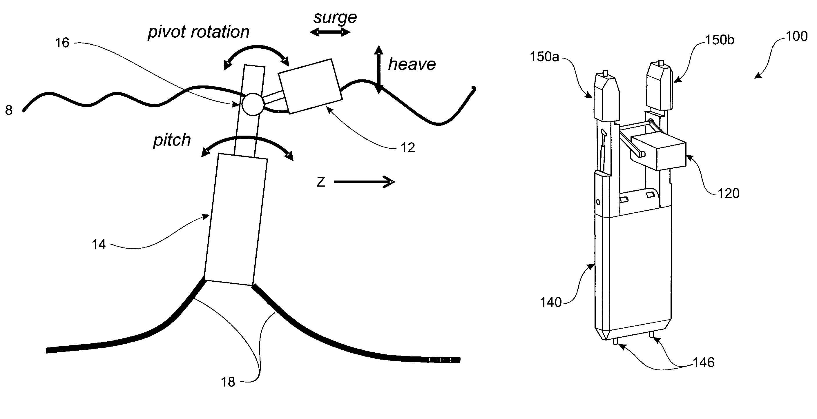
[0135]Referring to FIGS. 8a-8e, a first preferred embodiment of the wave energy converter 100 in the form of a 2 kW experimental device will be described.

2 kW Experimental Device—Active Float

[0136]The active float 120 is substantially elongate extending between a first 120a that is proximal to the reactive body 140 and a second 120b end that is distal to the reactive body. The cross-sectional area between the ends 120a,120b is defined peripherally by opposed top 120c and bottom 120d surfaces that are joined by opposed side surfaces 120e, 120f. The active float 120 has a uniform cross-sectional profile along its length, although it will be appreciated that a non-uniform profile could alternatively be used. The active float 120 has a length L1 of approximately 1.0 m, width W1 of approximately 0.7 m, and a depth D1 of approximately 0.5 m. The active float 120 has a dry weight of approximately 350 kg. The active float 120 is indirectly pivotably coupled to the re...

second preferred embodiment

100 kW Device

[0144]Referring to FIGS. 9a-9e, a second preferred embodiment of the wave energy converter 200 in the form of a 100 kW device will be described. The 100 kW device is similar in design to the experimental 2 kW device 100, but is larger in scale. The device 200 comprises an active float 220, reactive body 240 (with a main body 240a, and support arms 240b,c), and a sub-frame 222 for pivotably coupling the active float to the reactive body to enable relative pivotable movement between the bodies about pivot axis 260. The power output system may be as described previously and may be integrated into the support arms 240b,c of the reactive body 240.

[0145]The total length L7 of the reactive body 240 is approximately 20 m, with the length L5 of the support arms 240b,c being approximately 6.8 in and the length L6 of the main body 240a being approximately 13.2 m. The reactive body 240 has a width W3 of approximately 7.5 m and a depth D3 of approximately 1.6 m. The dry weight of th...


PUM


Abstract

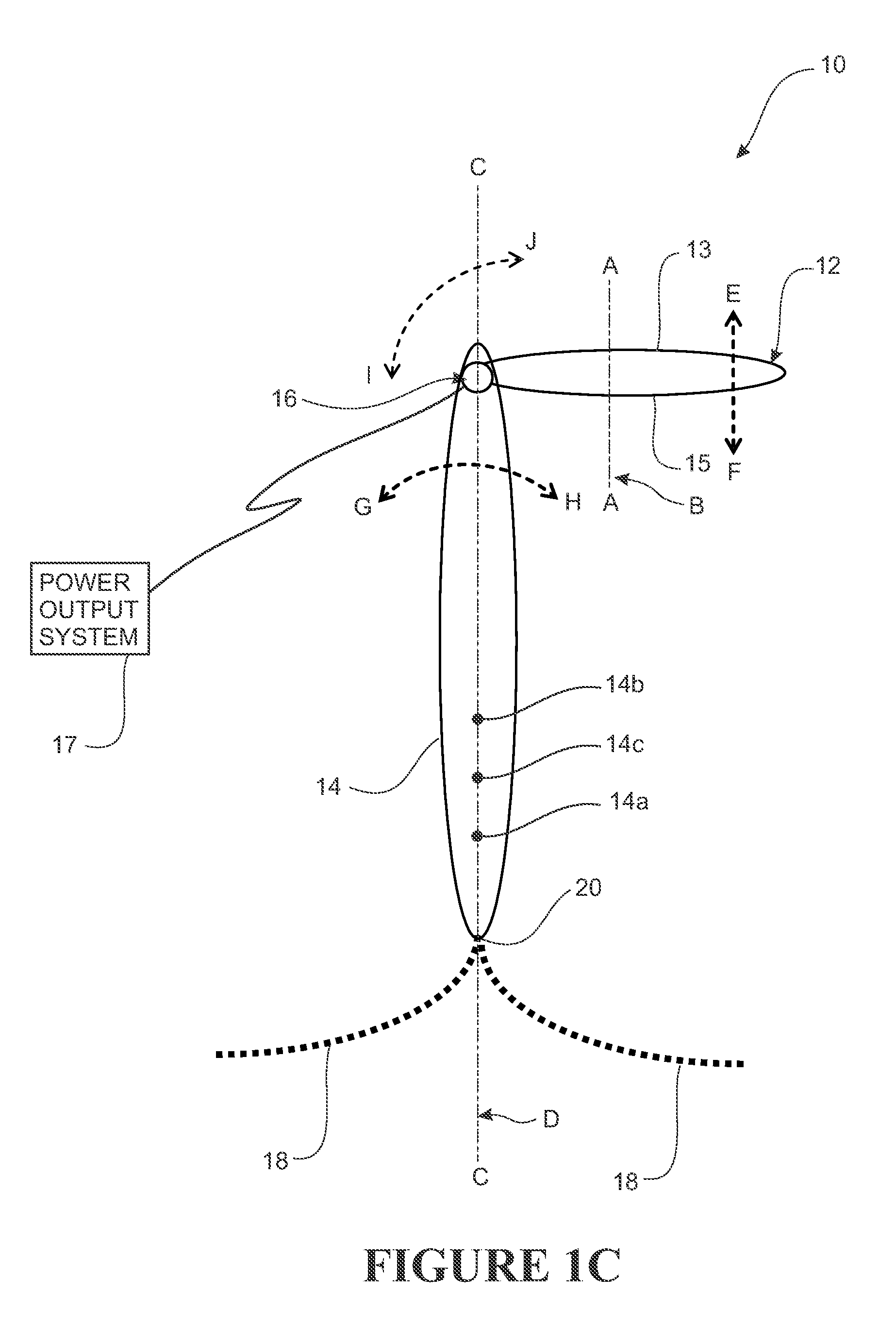
A wave energy converter (10) for extracting useful energy from wave motion. The converter (10) comprises an active float (12) that is arranged to float on the water, and being arranged to heave and surge in response to wave motion acting on the active float, and an elongate reactive body (14) that is arranged to be suspended in a substantially submerged state into the water and having sufficient surface area and length such that it pitches in response to wave motion-acting on the reactive body. The active float (12) and reactive body (14) are pivotably coupled for pivotable movement relative to each other about a single pivot axis (16) in response to heaving and surging of the active float and pitching of the reactive body. The converter also comprises a power output system that is driven by the pivotable movement about the pivot axis to capture the useful energy.

Description

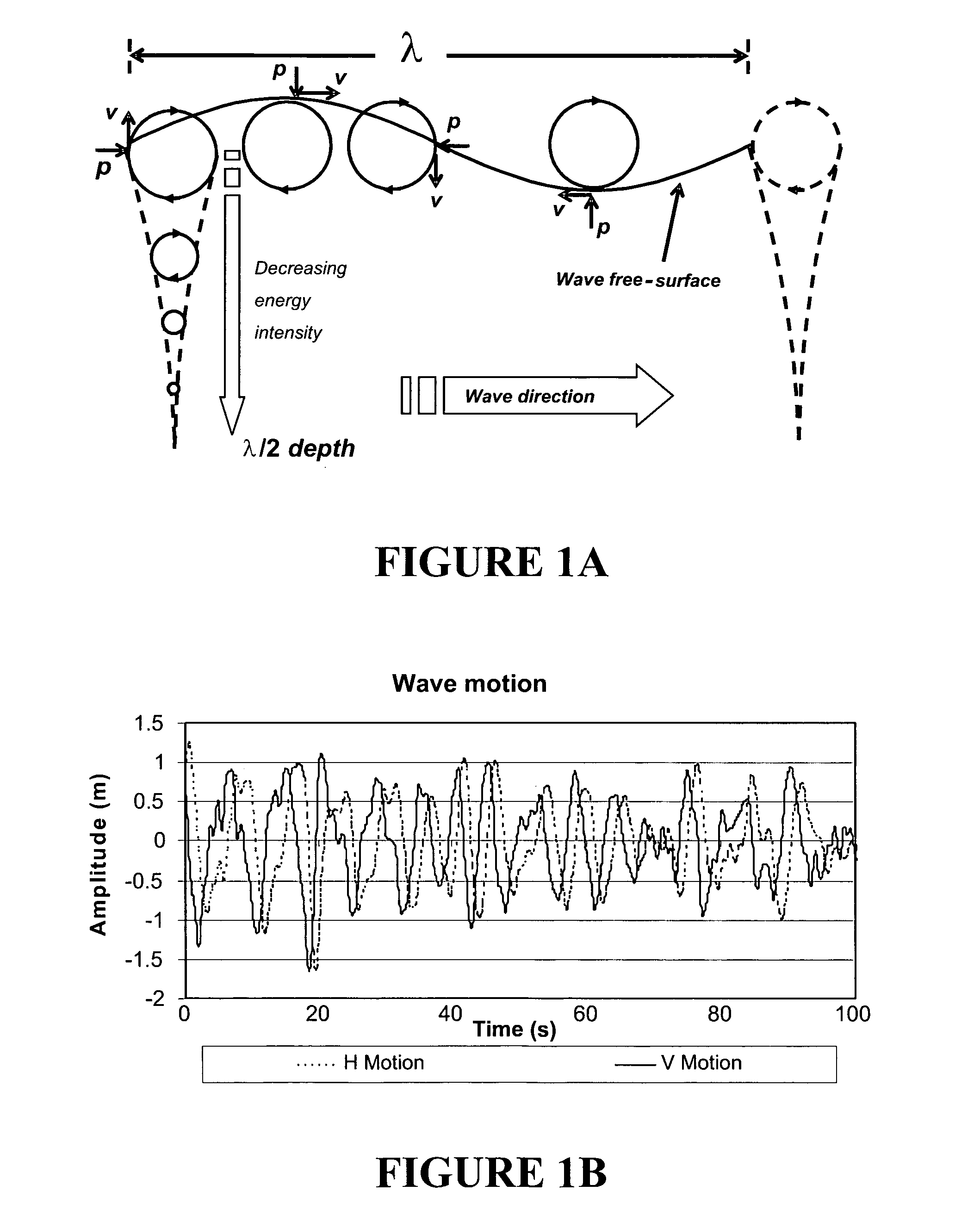
FIELD OF THE INVENTION[0001]The present invention relates to a wave energy converter. In particular, although not exclusively, the wave energy converter is capable of extracting useful energy, such as electrical energy for example, from wave motion in a body of liquid, such as but not necessarily the sea.BACKGROUND TO THE INVENTION[0002]Wave energy has been identified as one possible source of renewable energy. Various wave energy conversion devices have been proposed that aim to extract useful energy from wave motion in a body of liquid, such as the sea. Waves are created through the transfer of wind energy to the surface of bodies of water. Wave energy is propagated for long distances in deep water with minimal attenuation by interactive velocity and pressure fluctuations within the body of water. Fifty percent of the energy is propagated by pressure fluctuations and fifty percent by velocity fluctuations. A successful wave energy conversion device must maximise interaction with t...

Claims


Application Information

Patent Timeline
Patent Type & Authority Patents(United States)
IPC IPC(8): F03B13/12
CPCF03B13/16F03B13/1815Y02E10/38F05B2240/97F03B13/20Y02E10/30
Inventor GARDINER, ALISTERLE-NGOC, LANCAUGHLEY, ALAN
Owner CALLAGHAN INNOVATION
Learn More