Semiconductor component with trench isolation and corresponding production method
a technology of semiconductors and components, applied in the direction of semiconductor devices, basic electric elements, electrical equipment, etc., can solve the problems of undesirable leakage currents, insufficient conventional trench isolation, and no longer suitable conventional locos methods, so as to reduce the area requirement and improve the integration density
- Summary
- Abstract
- Description
- Claims
- Application Information
AI Technical Summary
Benefits of technology
Problems solved by technology
Method used
Image
Examples
first exemplary embodiment
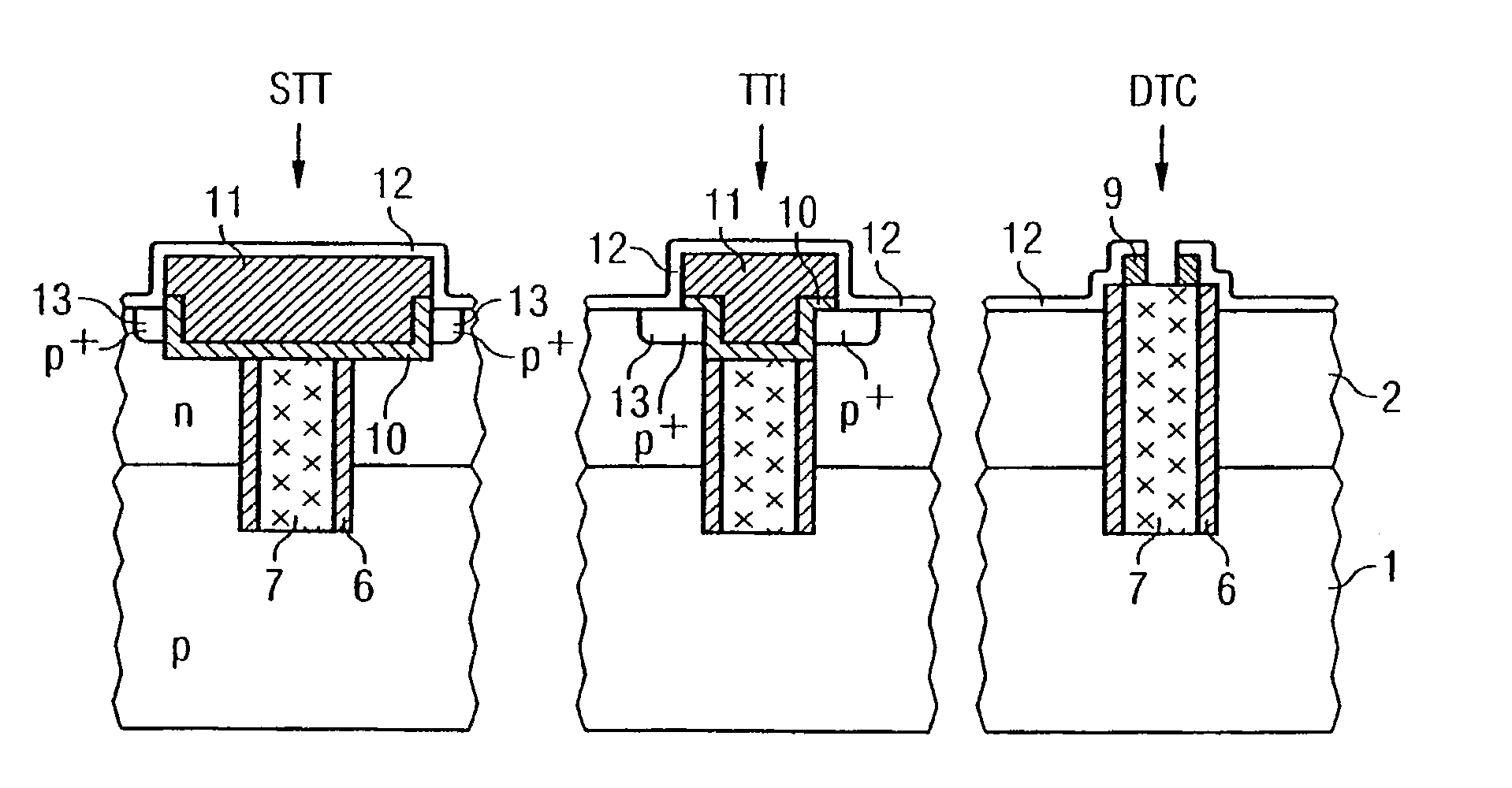
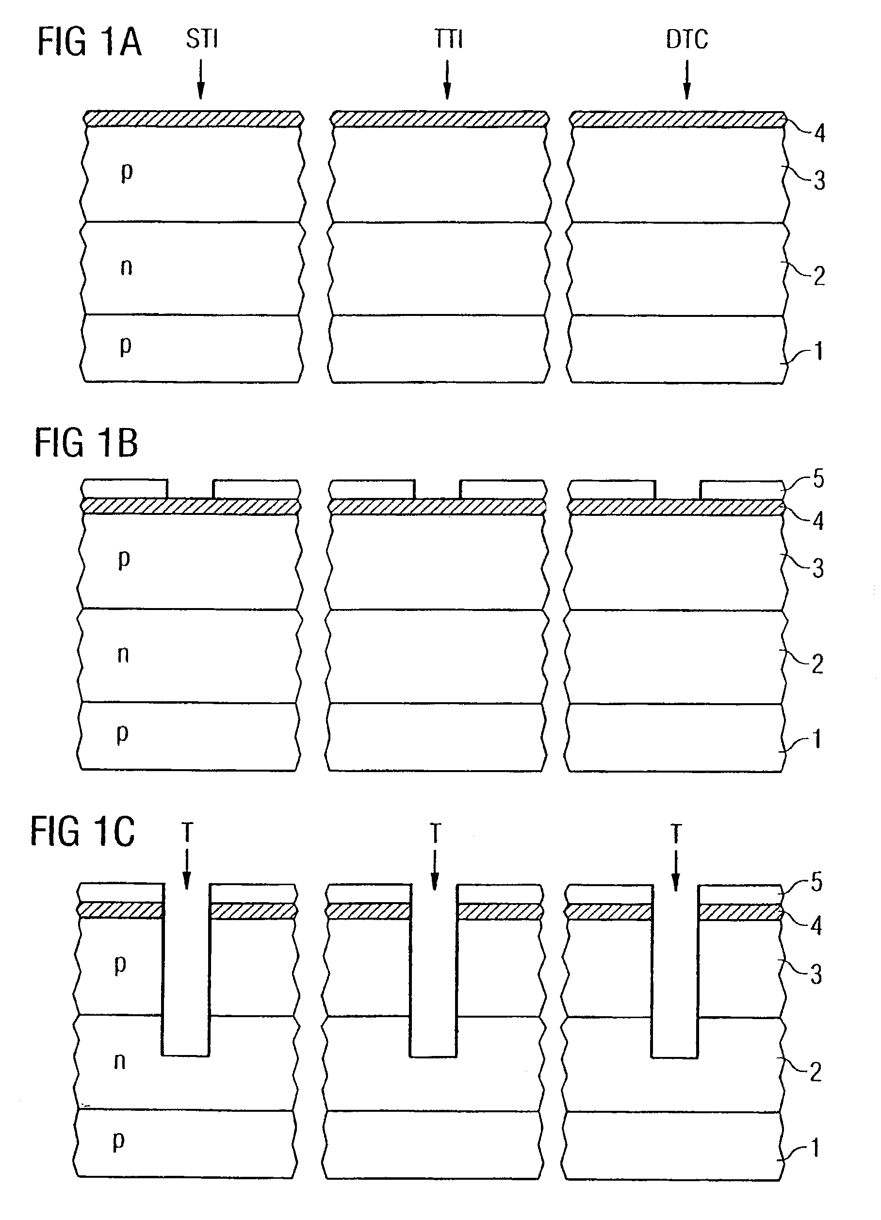
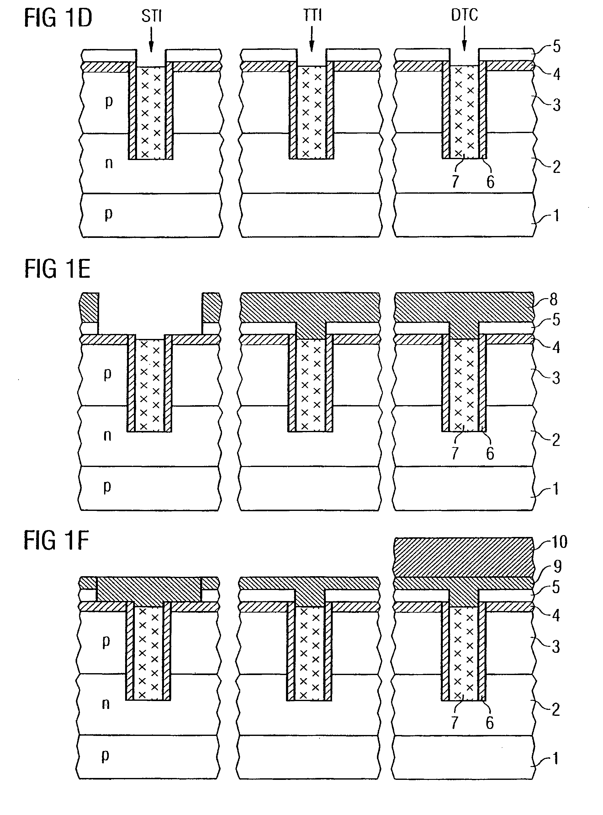
[0024]FIGS. 1A to 1N show simplified sectional views of a semiconductor component with a—in an upper region—widened but shallow trench isolation STI, a—in its upper region—thin trench isolation TTI and an associated trench contact DTC (Deep Trench Contact) in accordance with a first exemplary embodiment.
[0025]In accordance with FIG. 1A, firstly different doping regions are formed in a common carrier material such as e.g. a semiconductor substrate, the reference symbol 1 for example representing a p-type semiconductor substrate or a deep p-type well, the reference symbol 2 an n-type well and the reference symbol 3 a (shallow) p-type well. The wells or doping regions 1, 2 and 3 may be formed for example by means of ion implantation or other doping methods, silicon preferably being used as semiconductor material.
[0026]By way of example, a first insulation layer 4 in the form of an oxide layer is deposited or grown at the surface of the semiconductor substrate. A double or triple well s...
second exemplary embodiment
[0044]FIG. 2 shows a simplified sectional view of a semiconductor component with trench isolation in accordance with a second exemplary embodiment, identical reference symbols designating elements or layers identical or corresponding to those in FIG. 1, for which reason a repeated description is dispensed with below.
[0045]In accordance with FIG. 2, however, the semiconductor component may not only be formed in a semiconductor substrate with a multiple well structure, but rather may have merely a single doping, as a result of which, in particular for greatly simplified semiconductor circuits, improved shielding properties are likewise obtained with a reduced area requirement. The semiconductor component illustrated in FIG. 2 is an NMOS transistor, for example, a p-type semiconductor substrate 1 being used and, consequently, a p+-doped semiconductor material being used as electrically conductive filling layer. An improved connection possibility for the trench isolations that are conta...
third exemplary embodiment
[0047]FIG. 3 shows a simplified sectional view of a semiconductor component with trench isolation in accordance with a third exemplary embodiment, identical reference symbols designating elements or layers identical to those in FIG. 1 or 2 and a repeated description being dispensed with below.
[0048]In accordance with FIG. 3, the semiconductor substrate now has only a p-type well or an actual substrate 1 and an additional n-type well 2, the electrically conductive filling layer 7 being connected to the p-type well or the substrate 1. This yields an STI and TTI trench isolation for PMOS transistors, for which reason the doping regions 13 are p+-doped. Particularly when using highly doped semiconductor material, the electrically conductive filling layer is accordingly composed of a p′-doped polysilicon.
[0049]Improved shielding properties with a reduced area requirement again result in accordance with the first and secondary exemplary embodiment.
PUM
 Abstract
Description
Claims
Application Information
 - R&D
- Intellectual Property
- Life Sciences
- Materials
- Tech Scout
- Unparalleled Data Quality
- Higher Quality Content
- 60% Fewer Hallucinations
Browse by: Latest US Patents, China's latest patents, Technical Efficacy Thesaurus, Application Domain, Technology Topic, Popular Technical Reports.
© 2025 PatSnap. All rights reserved.Legal|Privacy policy|Modern Slavery Act Transparency Statement|Sitemap|About US| Contact US: help@patsnap.com


