Electrical control cable

a technology of electrical control cable and connector, which is applied in the direction of insulated cables, power cables, capacitors, etc., can solve the problems of copper becoming ever more expensive, polymer filaments making up the core run the risk of escaping radially between two copper strands, and excessive copper use, etc., to achieve reliable crimping of connectors and as inexpensive as possible to fabricate

Inactive Publication Date: 2014-04-08
NEXANS
View PDF11 Cites 17 Cited by
  • Summary
  • Abstract
  • Description
  • Claims
  • Application Information

AI Technical Summary

Benefits of technology

[0014]An object of the present invention is to provide a cable using just sufficient conductive material, typically copper, to ensure signal transmission, said material being shared amongst a limited number of strands, while also guaranteeing reliable crimping of a connector, and being as inexpensive as possible to fabricate.

Problems solved by technology

In contrast, it has been found that the above cable makes use of a quantity of copper that is excessive compared with the real requirements corresponding to the amount of electricity that is to be conveyed by the cable.
Unfortunately, copper is becoming ever more expensive, and it is important to find new cable structures that minimize the quantity of copper used to the smallest possible amount.
Merely replacing the central copper strand in the structure of FIG. 1 with a multifilament polymer core of the kind described in U.S. Pat. No. 7,145,082 is not appropriate since such a cable does not provide sufficient guarantees concerning crimping operations.
Once such a cable is stripped for a crimping operation, the copper strands splay apart from one another a little, and some of the polymer filaments making up the core run the risk of escaping radially between two copper strands.
Such a cable is expensive to fabricate, in particular because it uses a matrix of metal material for embedding the fibers.
Such a structure remains expensive to fabricate, because it uses said filler matrix.

Method used


Image

  • Electrical control cable
  • Electrical control cable
  • Electrical control cable

Examples


Embodiment Construction

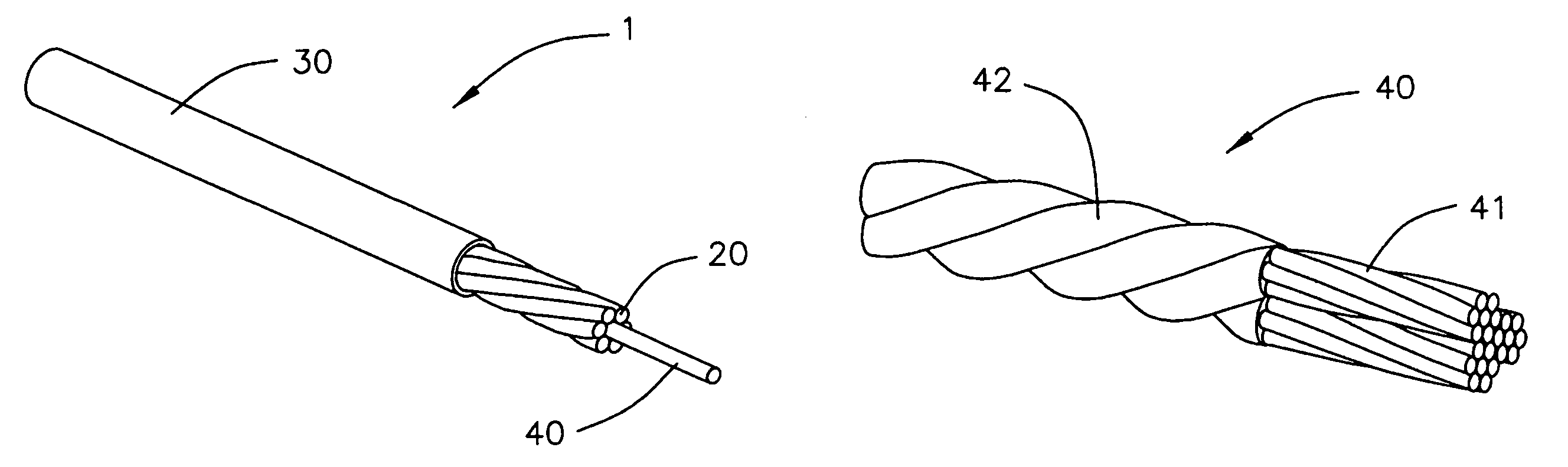
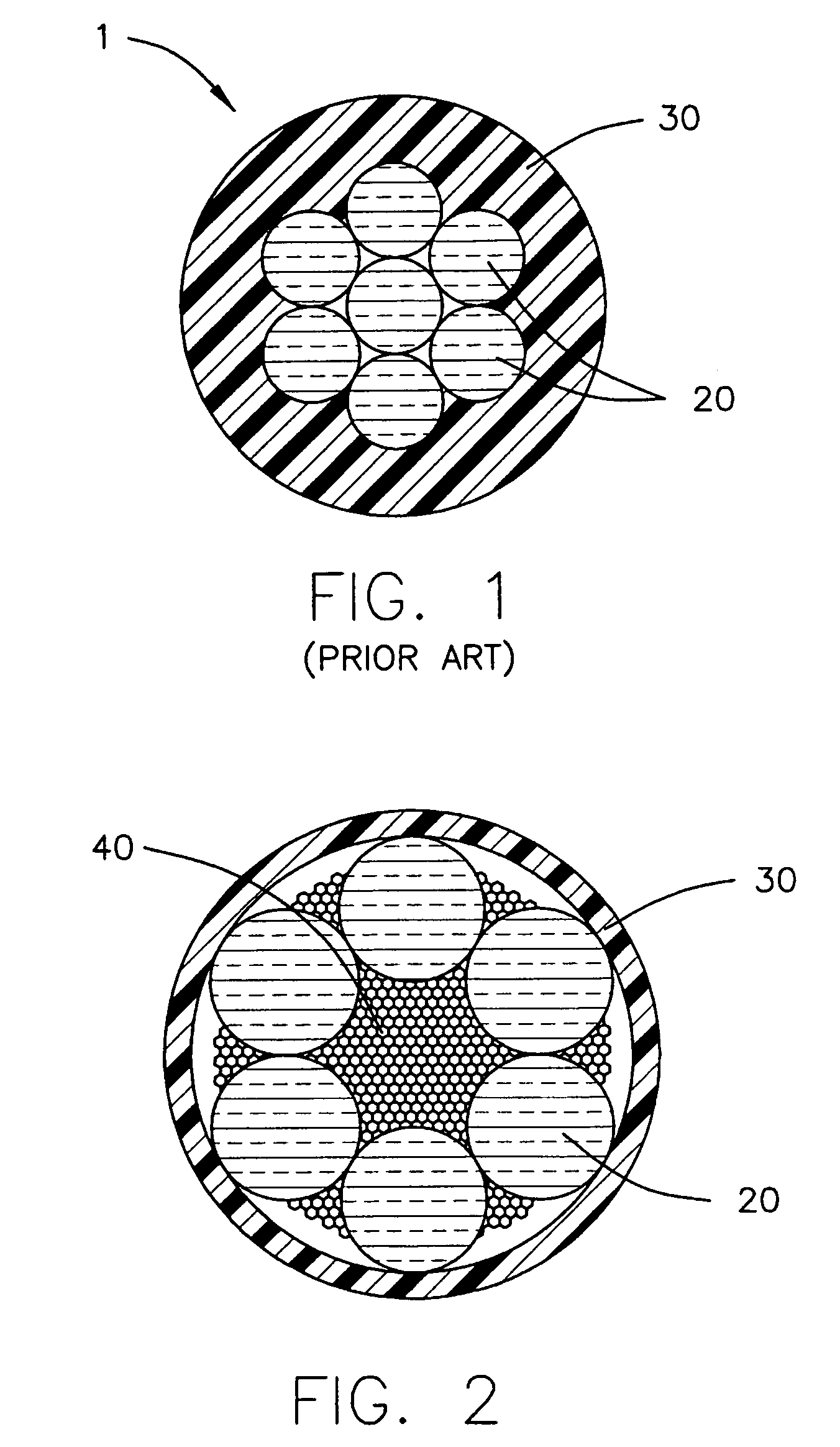
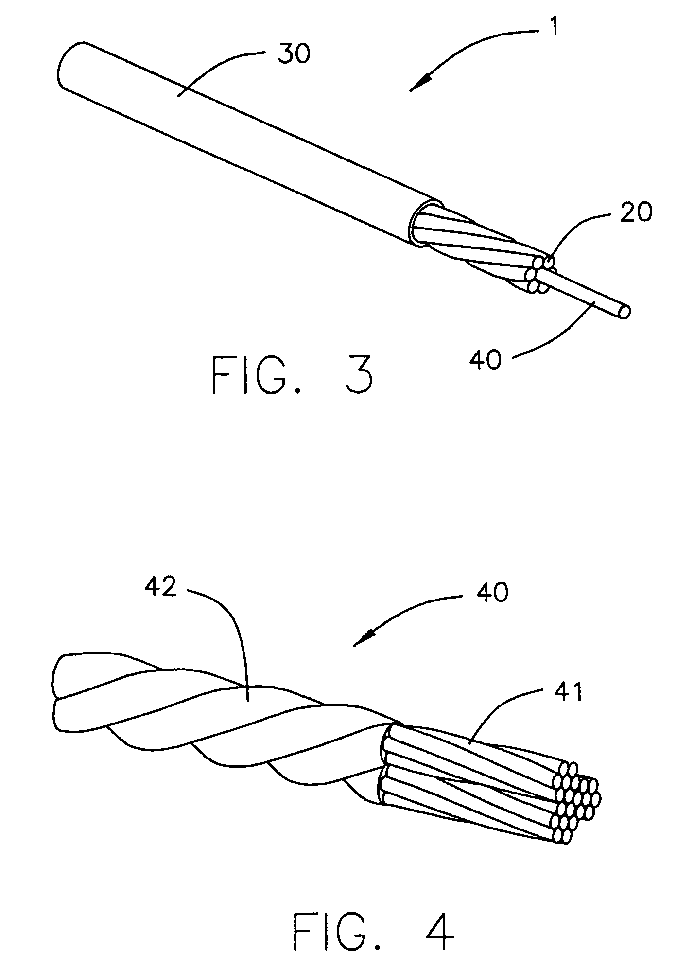
[0026]Like the prior art cable described in U.S. Pat. No. 7,145,082, the cable 1 of FIG. 3 comprises a plurality of strands 20 of conductive material, e.g. copper, extending in the longitudinal direction of a central core 40 of multifilament polymer, together with an outer sheath 30 of insulating material.

[0027]However, the number of strands 20 used is reduced since these strands are distributed uniformly and concentrically around said core 40, being in contact with one another in pairs and also with said core. In the non-limiting example shown, these strands 20 are six in number. For other sections of the core and of the strands, the total number of copper strands must naturally be adapted to surround the periphery of the core in a single layer.

[0028]The polymer filaments of the core 40, e.g. made of aramid, are secured to one another to constitute a non-metallic unitary structure, merely by means of an external adhesive coating. Such a step in the fabrication method is very easy t...


PUM

PropertyMeasurementUnit
diameteraaaaaaaaaa
diameteraaaaaaaaaa
conductoraaaaaaaaaa

Abstract

The present invention relates to an electrical control cable of the type comprising a core having a plurality of polymer filaments, a plurality of strands of conductor material extending in the longitudinal direction of said core, an outer insulating sheath. According to the invention, said strands are distributed uniformly and concentrically over the periphery of said core, in contact with one another in pairs and in contact with said core, and the filaments of said core are secured to one another to form a non-metallic unitary structure that is obtained by organizing said filaments into a plurality of subassemblies, the filaments in any one subassembly being twisted together helically, the subassemblies in turn being twisted with one another to form an overall helix. Advantage: the cable uses a limited number of copper strands while guaranteeing that crimping operations are reliable.

Description

RELATED APPLICATION[0001]This application claims the benefit of priority from French Patent Application No. 07 56639, filed on Jul. 20, 2007, the entirety of which is incorporated by reference.FIELD OF THE INVENTION[0002]The present invention relates to electrical control cables, or power cables, used for delivering electricity.BACKGROUND OF THE INVENTION[0003]Such cables are used in various fields in industry, such as, for example, the automobile industry, where they are assembled in bundles for electrically powering various pieces of equipment. Such cables thus need to be as lightweight as possible, and to be compact, while retaining good mechanical strength.[0004]Conventionally, such cables are made up of a plurality of copper strands, generally twisted together to form a twisted strand so as to increase the flexibility of the cable, and surrounded by an insulating sheath, e.g. obtained by extrusion. FIG. 1 shows an example of such a cable 1, seen in cross-section, and made from ...

Claims


Application Information

Patent Timeline
Patent Type & Authority Patents(United States)
IPC IPC(8): H01B5/10
CPCH01B7/0009H01B7/1825H01B9/00
Inventor DEBLADIS, FRANCISTRIBUT, LAURENTMORICE, STEPHANE
Owner NEXANS
Why Eureka
Try Eureka