

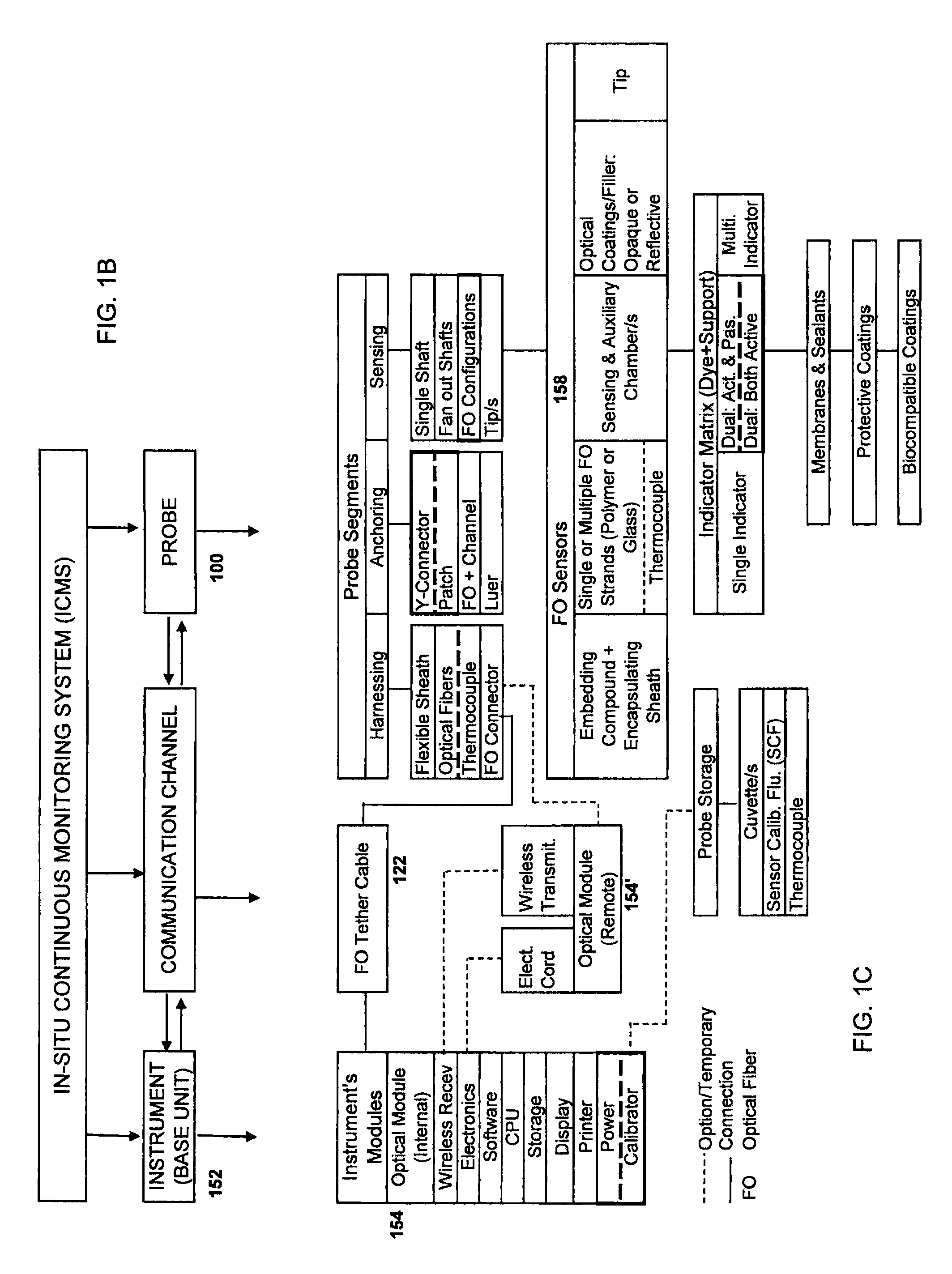
Fiber-optic probe with embedded peripheral sensors for in-situ continuous monitoring
a technology of fiber optic sensors and peripheral sensors, which is applied in the field of sensing probes employing fiber optic sensors, can solve the problems of reducing the efficiency of light transmission, restricting the use of sensors discussed in these patent documents, and existing designs from ensuring optimized operation
- Summary
- Abstract
- Description
- Claims
- Application Information
AI Technical Summary
Benefits of technology
Problems solved by technology
Method used
Image

Examples
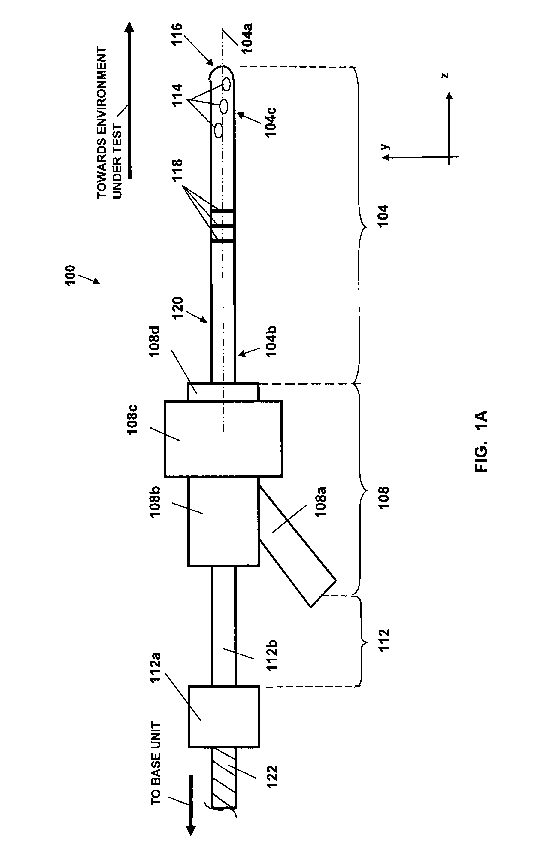
embodiment 100
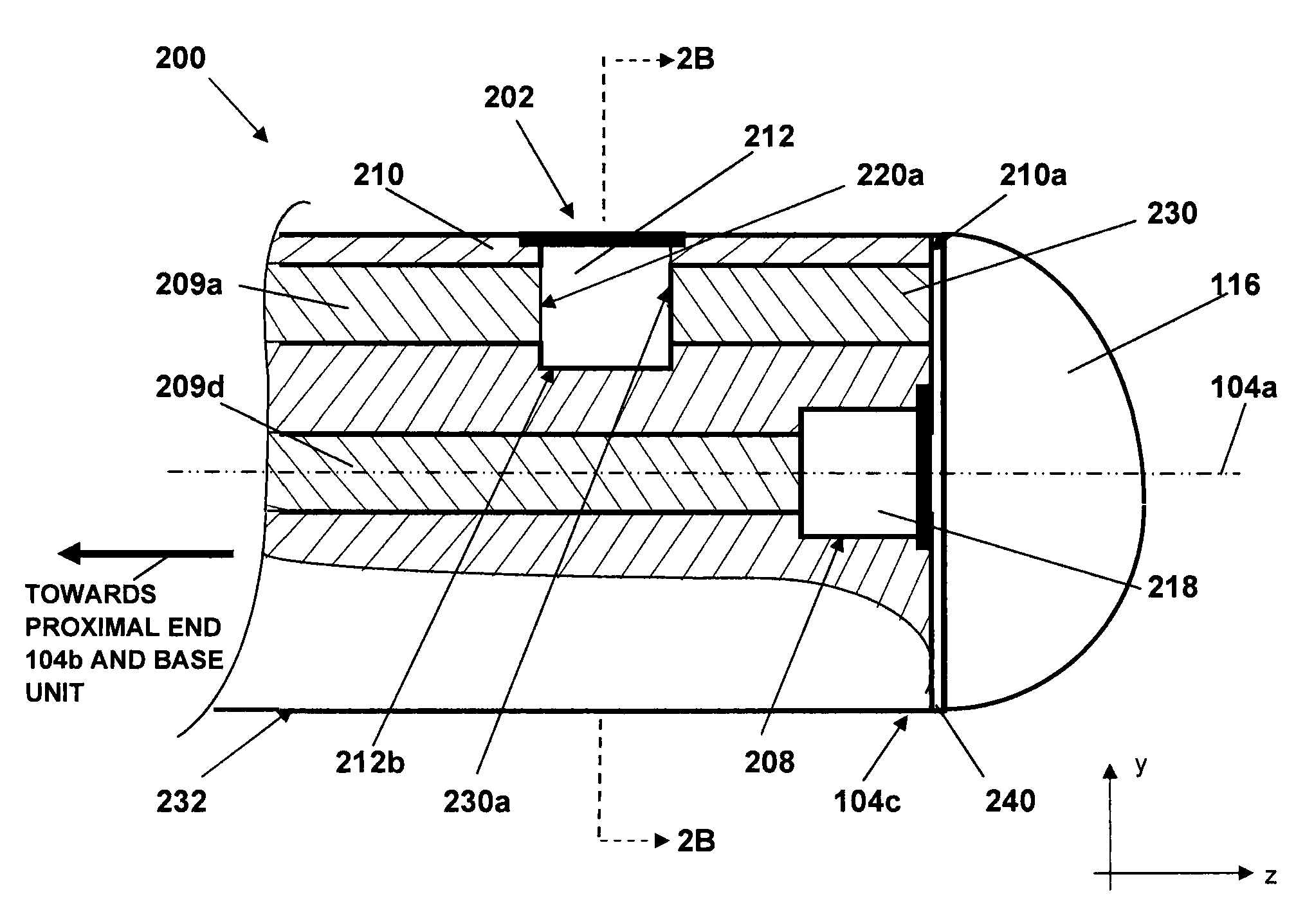
[0053]Each of the FO-element-based analyte sensor(s) and any physical-parameter sensor present in an embodiment are extended through the anchoring portion 108 and the harnessing portion 112 and further through an optional connector 112a towards a base unit (not shown) that incorporates photonic, mechanical, and computer sub-systems facilitating the operation of the embodiment 100. As discussed in more detailed elsewhere in this application, the sensing portion 104 may be equipped with membrane components and auxiliary optical and biological coatings.
[0054]In operation, the sensing portion 104 is at least partially inserted into a biological environment or medium the parameters of which are being measured with the embodiment 100. For example, the sensing portion 104 may be inserted into a living tissue subcutaneously or, alternatively, into a blood vessel such as an artery, or the brain, or a bodily cavity to enable a continuous in situ monitoring of analyst and physiological paramet...
embodiment 104
[0121]As shown in FIG. 10A, an embodiment 104 of the sensing probe is inserted in the tonometer solution 1012a by piercing of the stopper 1016 with a hollow needle 1030 through which the sensing probe 104 is protracted into the contents of the cuvette 1012. As such, the embodiment of the sensing probe is shipped from the factory. The jig-head 1020 is equipped with a sliding (for example, spring-loaded) and a rotating (m, for example, 120-degree steps, Ω) mechanisms (not shown) configured (i) to smoothly reposition the jig-head from one extreme position such as to retract, along the arrow 1024, the sensing portion 104 from its most recent position within a first cuvette such as the cuvette 1012, (ii) to incrementally rotate the jig-head 1020 about an axis 1040 so as to align the needle 1030 over an adjacent cuvette such as the cuvette 1014, and (iii) to smoothly reposition the jig-head 1020 along the arrow 1026 to bring the horizontal portion 1020a of the jig-head 1020 in close corre...
embodiment 1000
[0123]While, as shown and discussed in reference to FIGS. 10(A-D), the embodiment 1000 includes three cuvette-like containers facilitating a two-point calibration of the sensing probe, it is understood than a larger number of containers filled with respectively corresponding pre-determined buffer solutions may be used. In this case, the sliding and rotating mechanisms of the jig should be configured to accommodate appropriate incremental placement of the needle 1030 and the sensing portion of the probe 104 into each of the cuvettes of the jig.
[0124]According to embodiments of the invention, a synthesized buffer solution, or Sensor Calibration Fluid (SCF), is biocompatible, contains electrolytes, and is characterized with a pH value within a range compatible with physiological range of the electrolytes, bicarbonate, and osmolarity values. The SCF is also configured to be tonometered with a combination of gases (CO2 / N2 mixture) keeping a specific ionic strength and osmolarity. The SCF...
PUM
 Abstract
Description
Claims
Application Information