
System and method for subsurface characterization including uncertainty estimation

a subsurface and uncertainty estimation technology, applied in the field of methods and systems for characterization of subsurface formations, can solve the problems of general anisotropy of geological formations and inherent uncertainty in the resulting depth imag

Active Publication Date: 2014-04-08
CHEVROU USA INC
View PDF6 Cites 6 Cited by
  • Summary
  • Abstract
  • Description
  • Claims
  • Application Information

AI Technical Summary

Benefits of technology

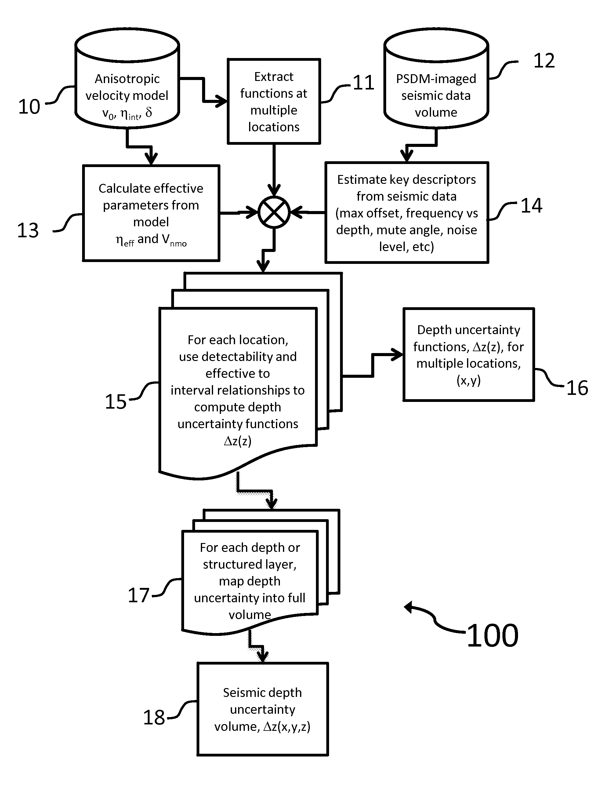
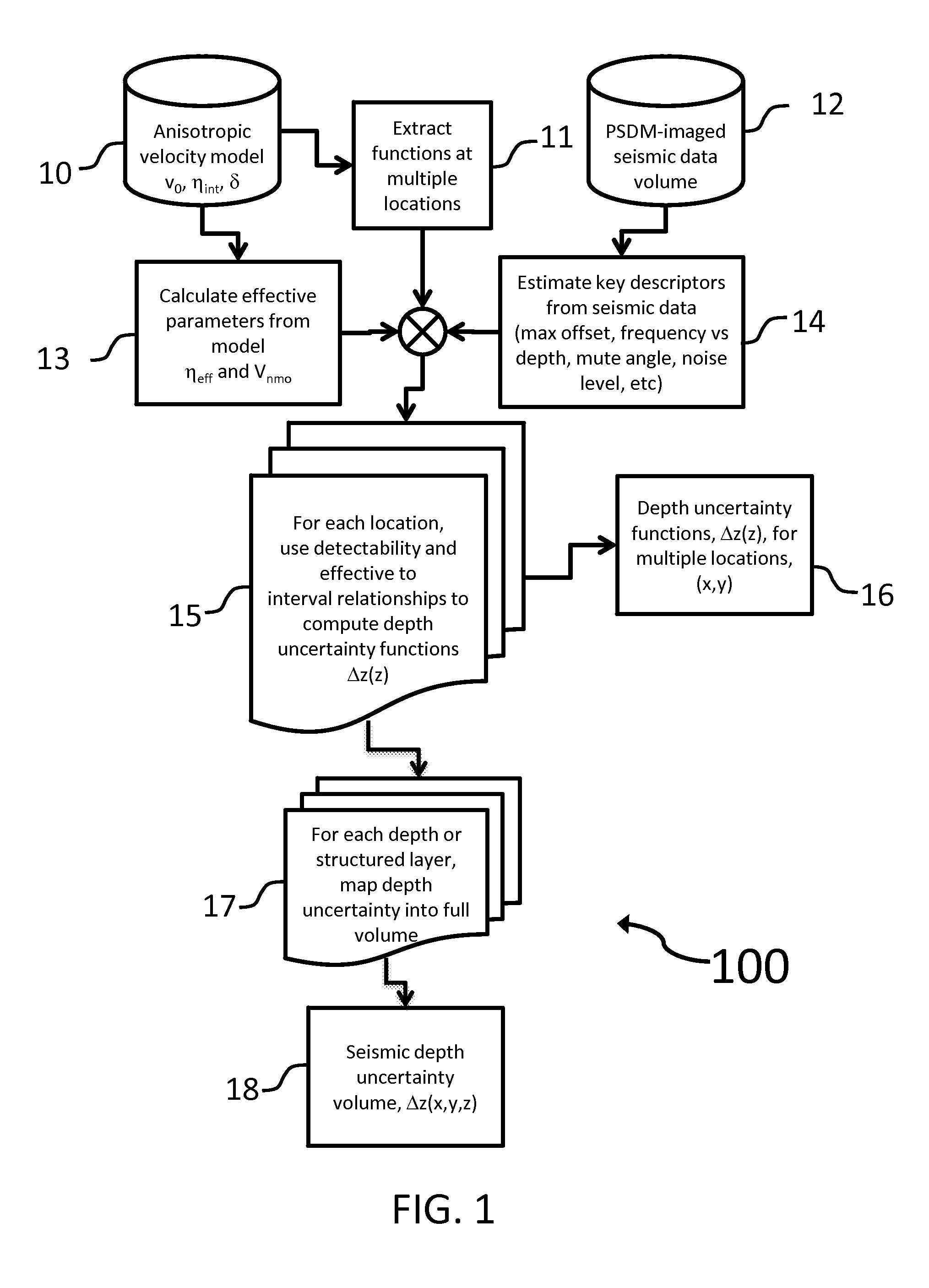
The patent describes a computer-implemented method for analyzing seismic data to determine the properties of the subsurface. The method involves receiving parameters and properties from an anisotropic seismic velocity model and key descriptors from the seismic data. It then calculates a depth uncertainty function to estimate the error in interpreting the seismic data. The method can also simulate multiple realizations to analyze changes in geometrical or structural properties of the subsurface. The technical effect of this invention is to provide a more accurate and reliable method for analyzing seismic data and interpreting the subsurface properties.

Problems solved by technology

Moreover, there is generally some degree of anisotropy in geological formations.
Finally, because assumptions, based on measurement or estimation, regarding both velocities and degrees of anisotropy may be incorrect, there is some inherent uncertainty in the resulting depth image, both in the depth of imaged events and in the structural interpretation of the events.
Uncertainty in the measurements results from a variety of sources, including signal-to-noise ratio, data acquisition parameter selection, processing algorithms, or the above mentioned velocity and anisotropy parameter selection.

Method used


Image

  • System and method for subsurface characterization including uncertainty estimation
  • System and method for subsurface characterization including uncertainty estimation
  • System and method for subsurface characterization including uncertainty estimation

Examples


Embodiment Construction

[0017]The present invention may be described and implemented in the general context of a system and computer methods to be executed by a computer. Such computer-executable instructions may include programs, routines, objects, components, data structures, and computer software technologies that can be used to perform particular tasks and process abstract data types. Software implementations of the present invention may be coded in different languages for application in a variety of computing platforms and environments. It will be appreciated that the scope and underlying principles of the present invention are not limited to any particular computer software technology.

[0018]Moreover, those skilled in the art will appreciate that the present invention may be practiced using any one or combination of hardware and software configurations, including but not limited to a system having single and / or multiple processor computers, hand-held devices, programmable consumer electronics, mini-co...


PUM


Abstract

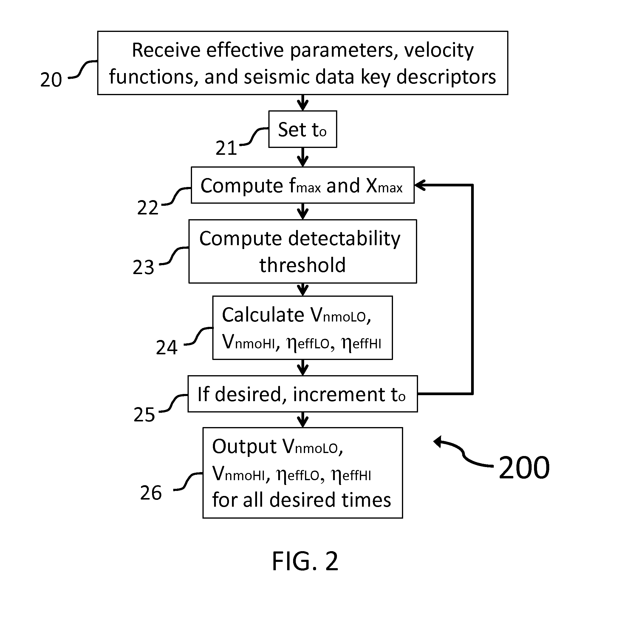
A system and method for subsurface characterization including depth and structural uncertainty estimation is disclosed. In one embodiment, the method may include determining a detectability threshold for moveout in a seismic data gather based on the seismic data and computing a depth uncertainty function, wherein the depth uncertainty function represents an error estimate that is used to analyze an interpretation of the seismic data. In another embodiment, the method may include receiving a depth uncertainty volume and at least one interpreted horizon from seismic data, extracting a depth uncertainty cage for each of the interpreted horizons based on the depth uncertainty volume, and simulating multiple realizations for each of the interpreted horizons, constrained by the depth uncertainty cage. The multiple realizations may be used for analyzing changes to geometrical or structural properties of the at least one interpreted horizon. The changes may be plotted as at least one distribution and may be used to make P10, P50 and P90 estimates.

Description

FIELD OF THE INVENTION[0001]The present invention relates generally to methods and systems for characterization of subsurface formations using seismic data and, in particular, methods and systems for subsurface characterization that estimate uncertainty in the depth or structure of the interpreted subsurface based on an anisotropic seismic velocity model.BACKGROUND OF THE INVENTION[0002]Oil and gas prospect evaluation and field development require accurate characterization of subsurface features. Seismic acquisition over subsurface structure generally produces time-domain data, which is then migrated to, for example, depth image data. The migration process necessarily involves certain assumptions regarding the propagation velocity of elastic waves through the subsurface materials and structures. Moreover, there is generally some degree of anisotropy in geological formations. That is, while it may be possible to determine vertical velocities using well data, the velocities estimated ...

Claims


Application Information

Patent Timeline
Patent Type & Authority Patents(United States)
IPC IPC(8): G06F19/00G01V1/28G01V1/30
CPCG01V1/305G01V1/301G01V2210/667G01V2210/6222G01V2210/626
Inventor SCHULTZ, PHILIP STEPHANHOELTING, CORY JAMES
Owner CHEVROU USA INC
Learn More