
Parameter setting method of bearingless motor drive system with fractional order PID

A bearingless motor and drive system technology, applied in the direction of electric controllers, controllers with specific characteristics, etc., to achieve the effect of improving precision, good accuracy and stability

Inactive Publication Date: 2019-08-13
SUZHOU APP SCI ACAD CO LTD
View PDF7 Cites 2 Cited by
  • Summary
  • Abstract
  • Description
  • Claims
  • Application Information

AI Technical Summary

Problems solved by technology

[0004] After retrieving relevant domestic and foreign literature and patents, the D-stable domain of fractional-order PID determined by the D-segmentation method has never been applied to the control of bearingless motor drive systems.

Method used


Image

  • Parameter setting method of bearingless motor drive system with fractional order PID
  • Parameter setting method of bearingless motor drive system with fractional order PID
  • Parameter setting method of bearingless motor drive system with fractional order PID

Examples


Embodiment Construction

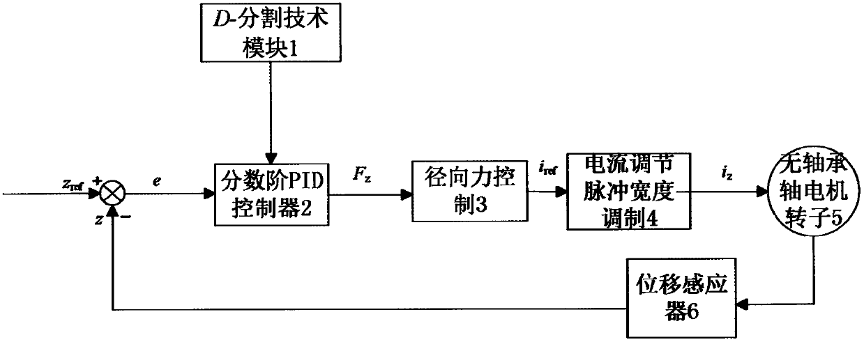
[0016] see figure 1 Shown is the overall block diagram of the control system of the stable domain method of the fractional-order PID described in the present invention, the radial displacement of the bearingless motor rotor 5 is detected by the displacement sensor 6, the displacement sensor 6 outputs the displacement output signal z, and the displacement output Signal z and given reference position signal z ref Compare and get the deviation e of the two. The obtained deviation result e is adjusted by the fractional order PID controller 2 processed by the D-division technology module 1 to output the force signal F z to the radial force control module 3, and then output the current reference signal i ref , the signal i ref Output the control current i via the current regulation pulse width modulation module 4 z Drive the control coil of the rotor 5 of the bearingless motor, thereby realizing the closed-loop control of the rotor of the bearingless motor.

[0017] The transfe...


PUM


Abstract

The invention discloses a parameter setting method of a bearingless motor drive system with a fractional order PID. The method selects an additive uncertainty function to suppress external disturbances by adopting the fractional order PID combined with a D-segment method, so as to improve stability. In the method, a D-segmentation technical module, a fractional order PID controller, a radial forcecontrol module, a current-adjusting pulse width modulation module, a bearingless motor rotor and a displacement sensor detection circuit are mainly provided, wherein the radial displacement of the bearingless motor rotor is detected by the displacement sensor; the displacement sensor outputs a displacement output signal z, which is compared with a given reference position signal zref to obtain adeviation e between the two; after the obtained deviation result e is adjusted by the fractional order PID controller processed by the D-segmentation technical module, a force signal Fz is output to the radial force control module, and a current reference signal iref is further output; and the signal iref is output by the current-adjusting pulse width modulation module to control control the current iz to drive the control coil of the bearingless motor rotor, thereby achieving closed-loop control of the bearingless motor rotor.

Description

technical field [0001] The invention relates to a parameter setting method of a bearingless motor drive system, which can be used for military equipment such as artificial satellites and missiles, as well as high-reliability and stable control systems for flywheel energy storage, generators, and artificial heart pumps in the field of high-speed and high-precision motor transmission. etc., which belong to the field of electric drive control equipment and mechanical lubrication and sealing technology. Background technique [0002] The bearingless motor is a magnetic AC levitation motor with a novel structure. Compared with ordinary high-speed motors, it has the advantages of high speed, no wear, long life, and no need for lubrication. Its control system is more complicated, and it is difficult to control the stable suspension of the rotor. Magnetic bearings are widely used in power transmission fields such as flywheel energy storage, high-speed high-precision motors, and arti...

Claims


Application Information

Patent Timeline
IPC IPC(8): G05B11/42
CPCG05B11/42
Inventor 胡德霖杨益飞王林张敏李杰
Owner SUZHOU APP SCI ACAD CO LTD
Learn More