Portable diaper-changing restraint system

a technology of diaper changing and restraints, which is applied in the field of diaper products, can solve the problems of reducing the ability of the baby to turn, and achieve the effect of limiting the movement of the baby

Inactive Publication Date: 2014-04-15
HANSON LISA CASH
View PDF30 Cites 30 Cited by
  • Summary
  • Abstract
  • Description
  • Claims
  • Application Information

AI Technical Summary

Benefits of technology

[0006]The cover-encased body of the diapering restraint is placed around the waist of the baby with the blunt ends positioned on the surface upon which the baby is lying. A strap extends under the baby from the first cantilever arm to the second cantilever arm to secure the baby within the central U-shaped opening. The diaper-changing restraint system retains the baby's hands on the front side of the diapering restraint, holding them away from the diaper area, while reducing the ability of the baby to turn.
[0008]In use, the portable diaper-changing restraint system comfortably limits the baby's movement and shields the baby's hands from accessing the diaper area, while providing a distraction or diversion to occupy the baby's attention for the time required for changing a diaper.
[0009]An object of the present invention is to provide a diaper-changing restraint system that is comfortable for the baby.
[0010]An additional object is to provide a diaper-changing restraint system that retains the baby's hands on the forward side of the diaper-changing restraint system, preventing the hands from reaching the diaper area.
[0011]A further object is to provide a diaper-changing restraint system that limits the baby's movements.

Problems solved by technology

The diaper-changing restraint system retains the baby's hands on the front side of the diapering restraint, holding them away from the diaper area, while reducing the ability of the baby to turn.

Method used


Image

  • Portable diaper-changing restraint system
  • Portable diaper-changing restraint system
  • Portable diaper-changing restraint system

Examples


first embodiment

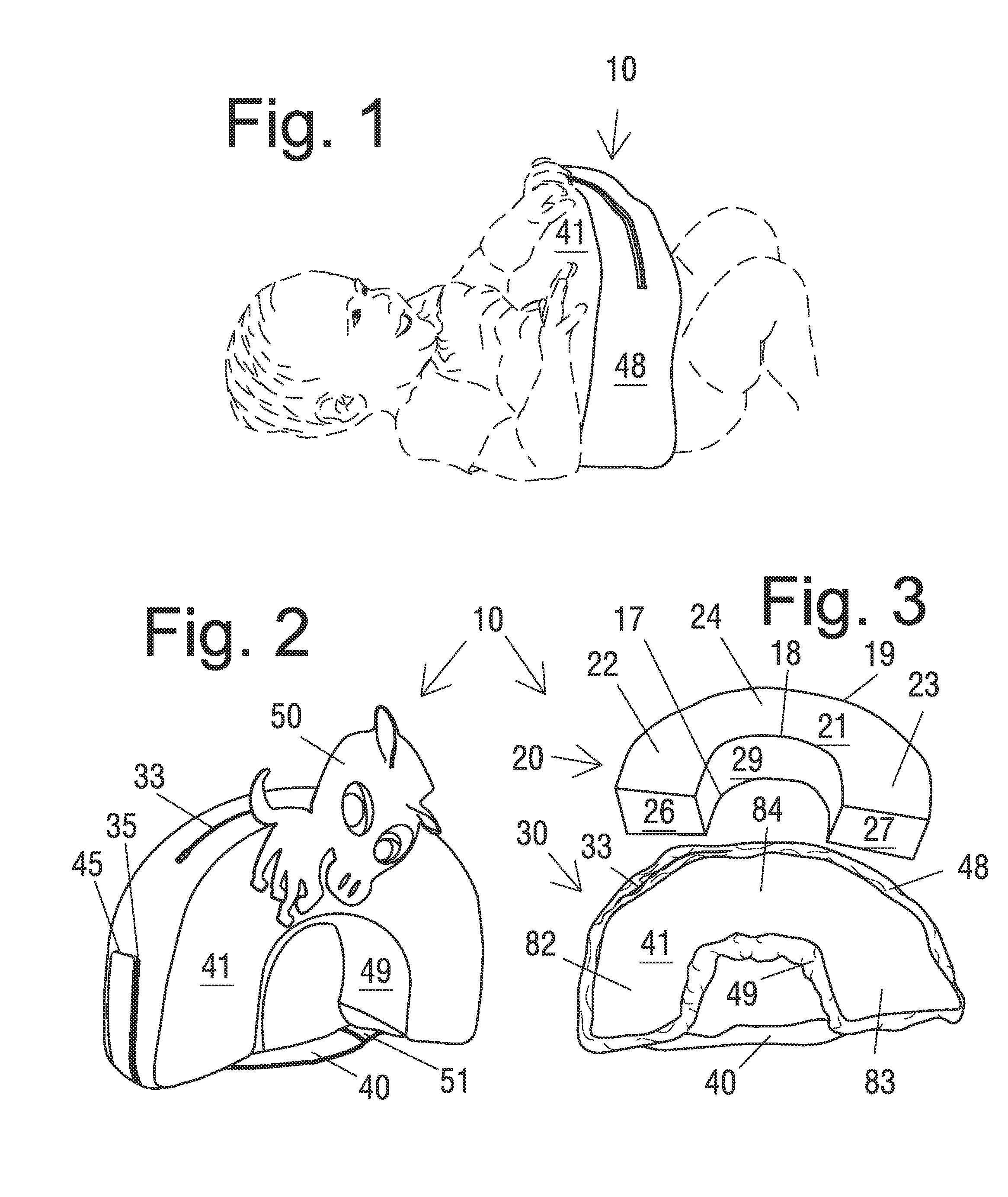
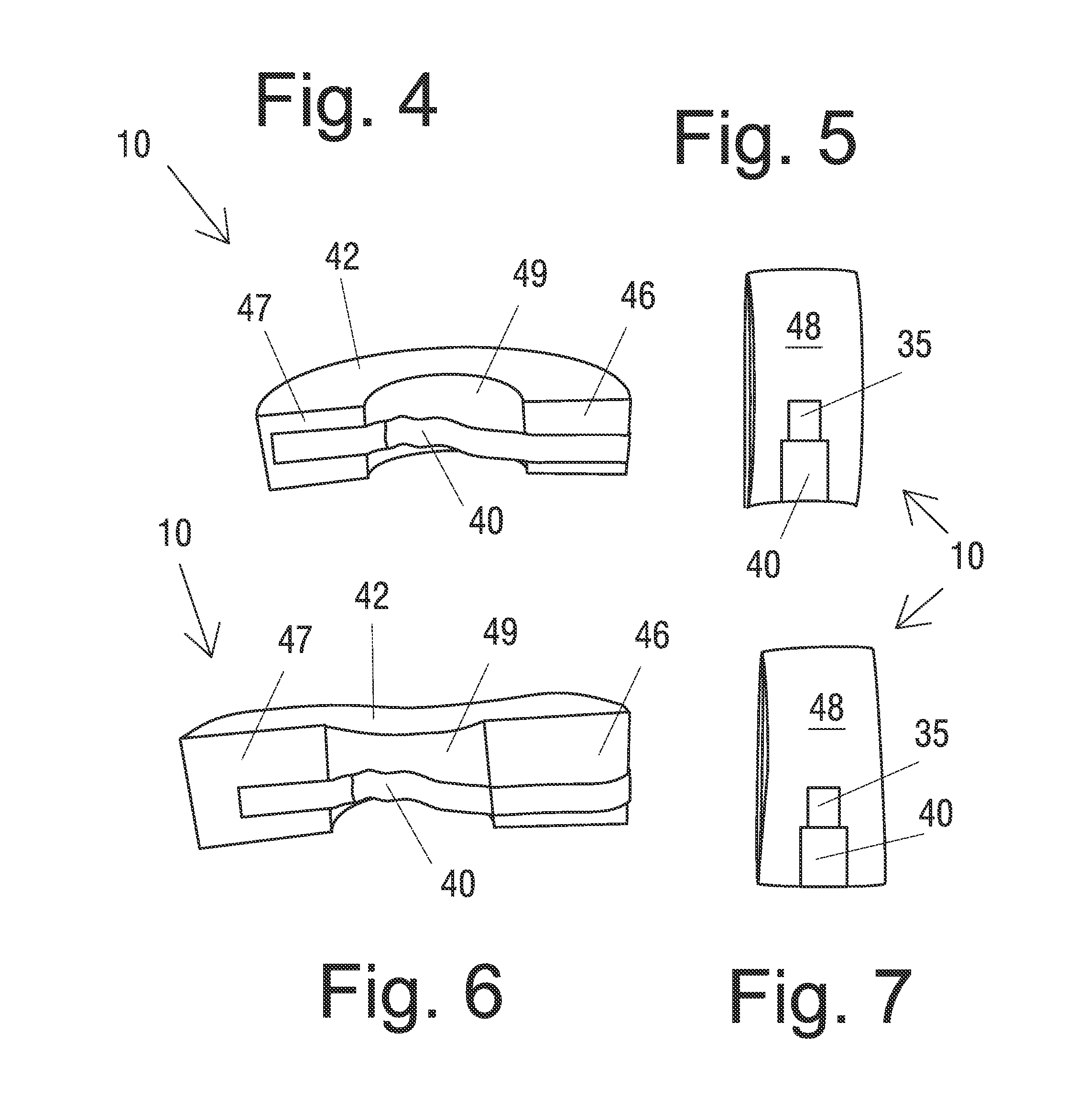
[0032]The U-shaped body 20 includes a front surface 21 (FIG. 3); a back surface (under cover back surface 42, as seen in FIG. 4); an outer side / top wall (under cover outer side / top wall 48, as seen in FIG. 1) having a back edge and a front edge 18; and an inner bottom wall 29 having a back edge 17 and a front edge 18. The front surface 21 extends from the front edge 19 of the outer side / top wall to the front edge 18 of the inner bottom wall 29. In the first embodiment, the outer side / top wall has an approximately constant horizontal thickness which is equal to the approximately constant horizontal thickness of the inner bottom wall 29, thus the body 20 is substantially flat and equal in thickness throughout.

[0033]The removable cover assembly 30 (FIG. 3) is configured to fully enclose the U-shaped body 20. The cover assembly 30 has a front surface 41, a back surface 42 (FIG. 4), a first cantilever arm end 46, a second cantilever arm end 47, an inner bottom wall 49, and an outer side / ...

fourth embodiment

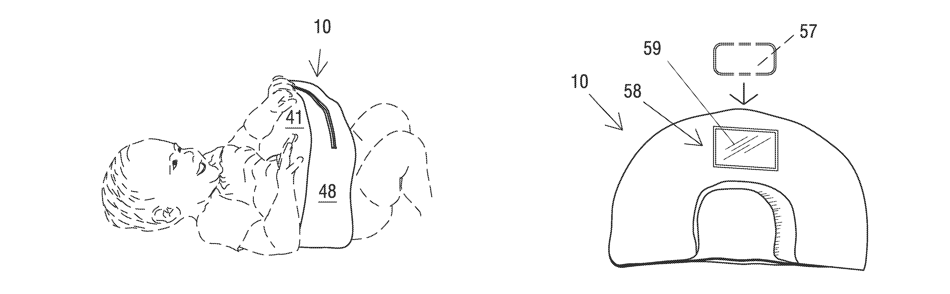
[0039]FIG. 9 illustrates the diaper-changing restraint system, which includes one or more connections 45 for removably attaching a connectable accessory, such as a distraction device 50, 69 or a removable pocket 68 (configured for receiving a mobile phone 57). Suitable exemplary connectable accessories are shown in FIG. 10; they are configured with a corresponding connection device 55. Connection devices 45 are shown in FIG. 9 as loops and corresponding connection device 55 is shown as a C-shaped link which may be attached to the loop. However, other connection devices 45 and corresponding connection devices 55, as are known or become known in the art are also usable. For example, connection devices 45 may be a hard plastic hook, a section of hook and loop material, or the like.

[0040]In the fifth embodiment, the portable diaper-changing restraint system comprises both diapering restraint 10 and a restraint-receiving bag 60. As shown in FIG. 11, bag 60 is sized and configured for rec...

sixth embodiment

[0041]In the sixth embodiment, the portable diaper-changing restraint system also comprises both diapering restraint 10 and a restraint-receiving bag 60. FIGS. 12-13 illustrate a second variation of bag 65 for receiving and transporting the restraint device 10 of the present invention. The second bag 65 is configured with opposing sides 66 and a center section 68. Handles 64 are preferably included for ease of carrying. The sides 66 generally conform to, but are slightly larger than, the U-shape of the body 20; therefore, sides 66 have a generally half-oval shape. The center section 68 is configured and sized to receive the ends 26, 27 of the body 20. Therefore, center section 68 has a width slightly greater than the width of the ends 26, 27 and a length slightly greater than the length between the outside edges of the ends 26, 27. FIG. 12 shows the bag enclosing the restraint device 10, while FIG. 13 shows the bag 65 opened with the restraint device 10 removed. As shown in FIG. 13,...


PUM


Abstract

A portable diaper-changing restraint system is provided that includes a resilient, substantially U-shaped body having two cantilever arms and a removable cover assembly configured to fully enclose the U-shaped body. The cover assembly includes a strap having a first end attached or attachable to one arm and having a second end configured with an attached fastening device for attaching to the opposing arm. In use, the infant is positioned on the strap with the U-shaped body brought over and onto the infant's waist; then the strap is attached. Thus the U-shaped body is positioned around the infant's torso with the ends of the cantilever arms resting on the surface upon which the baby is lying, reducing the ability of the infant to turn and holding the infant's hands away from the diaper area.

Description

FIELD OF INVENTION[0001]This invention relates generally to baby products, and, more particularly, to a portable diaper-changing restraint system with a resilient inner body for fitting around an infant's torso.BACKGROUND OF THE INVENTION[0002]Changing an infant's diaper is often challenging to parents or other caregivers. Holding the baby's legs with one hand while the other hand simultaneously cleans the baby and reaches for all of the items needed is taxing, but it is particularly difficult when changing a dirty diaper. Caregivers need the baby to remain still to efficiently and sanitarily change the diaper. Yet, babies enjoy freedom and movement. Thus, they are likely to resist being held still during the process. The uncooperative baby may attempt to roll over, to sit up, or to place his hands in the diaper area, risking contamination of additional surfaces.[0003]To address this problem, a variety of diaper-changing aids have been developed. Many of the diaper-changing devices ...

Claims


Application Information

Patent Timeline
Patent Type & Authority Patents(United States)
IPC IPC(8): A61B19/00A47D13/08
CPCA47D15/008A47D15/006A47D13/08A61B19/00A47D5/00
Inventor HANSON, LISA, CASH
Owner HANSON LISA CASH
Why Eureka
Try Eureka