Fishing reel handle assembly

a technology for reels and handle parts, applied in the direction of reels, mechanical control devices, instruments, etc., can solve the problems of affecting the quality of fishing reels, the inability of fishing reels to ensure sufficient strength, and the difficulty of burying metal components in fiber-reinforced resins, etc., to achieve easy formation and high strength

Active Publication Date: 2014-04-15
SHIMANO INC
View PDF18 Cites 2 Cited by
  • Summary
  • Abstract
  • Description
  • Claims
  • Application Information

AI Technical Summary

Benefits of technology

[0011]In the fishing reel handle assembly, the handle arm includes the main body and the convexo-concave portion. The main body extends in a direction intersecting with the axial direction of the handle shaft. The main body is formed by laminating the plurality of sheets of prepreg. The convexo-concave portion is convexly or concavely formed on either the front surface of the main body or the back surface of the main body, i.e., the surface opposite to the front surface. In this case, the handle arm can be lightweight due to the structure in which the main body of the handle arm is formed by laminating the plurality of sheets of prepreg. Further, a section strength modulus of the handle arm can be increased in a longitudinal direction of the handle arm and the handle assembly can thereby maintain high strength in the axial direction of the handle shaft due to the structure in which the convexo-concave portion is formed on either the front surface of the main body of the handle arm or the back surface of the main body of the handle arm, i.e., the surface opposite to the front surface. Consequently, the handle arm can be prevented from being broken and damaged even when a large force acts on the handle arm in the axial direction of the handle shaft. Further, a metal member is not required to be buried in the handle arm unlike the well-known handle arm assembly.
[0022]According to the fishing reel handle assembly, the handle arm includes the main body and the convexo-concave portion. The main body herein extends in a direction intersecting with the axial direction of the handle shaft. The main body is formed by laminating the plurality of sheets of prepreg. The convexo-concave portion is convexly or concavely formed on at least either of the front surface of the main body and the back surface of the main body, i.e., the surface opposite to the front surface. Therefore, the handle arm can be lightweight. Simultaneously, the handle arm can maintain high strength in the axial direction of the handle shaft.

Problems solved by technology

When actually made of a fiber-reinforced resin, the handle arm may not ensure sufficient strength particularly in a lamination direction of plural fiber-reinforced resin layers.
The handle arm may be thereby damaged when a large force acts on the handle arm in the axial direction of the handle shaft.
However, it is generally technically difficult to bury a metal component in a fiber-reinforced resin.

Method used


Image

  • Fishing reel handle assembly
  • Fishing reel handle assembly
  • Fishing reel handle assembly

Examples


Embodiment Construction

[0037]Selected embodiments will now be explained with reference to the drawings. It will be apparent to those skilled in the art from this disclosure that the following descriptions of the embodiments of the present invention are provided for illustration only and not for the purpose of limiting the invention as defined by the appended claims and their equivalents.

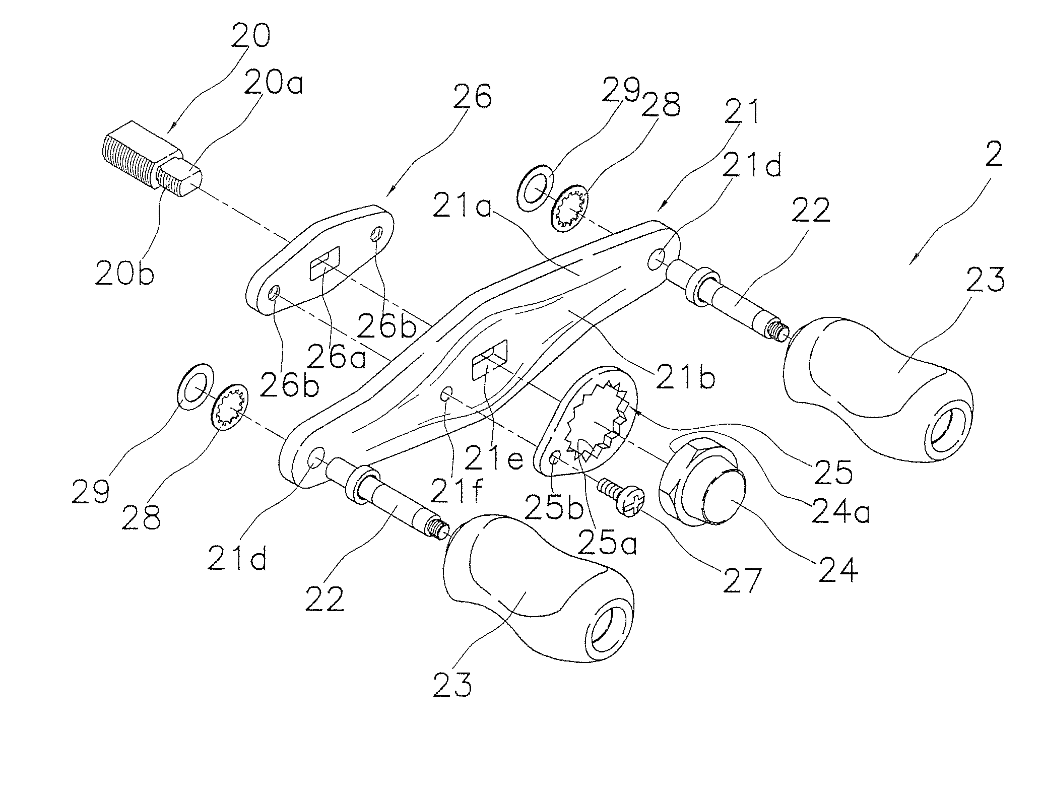
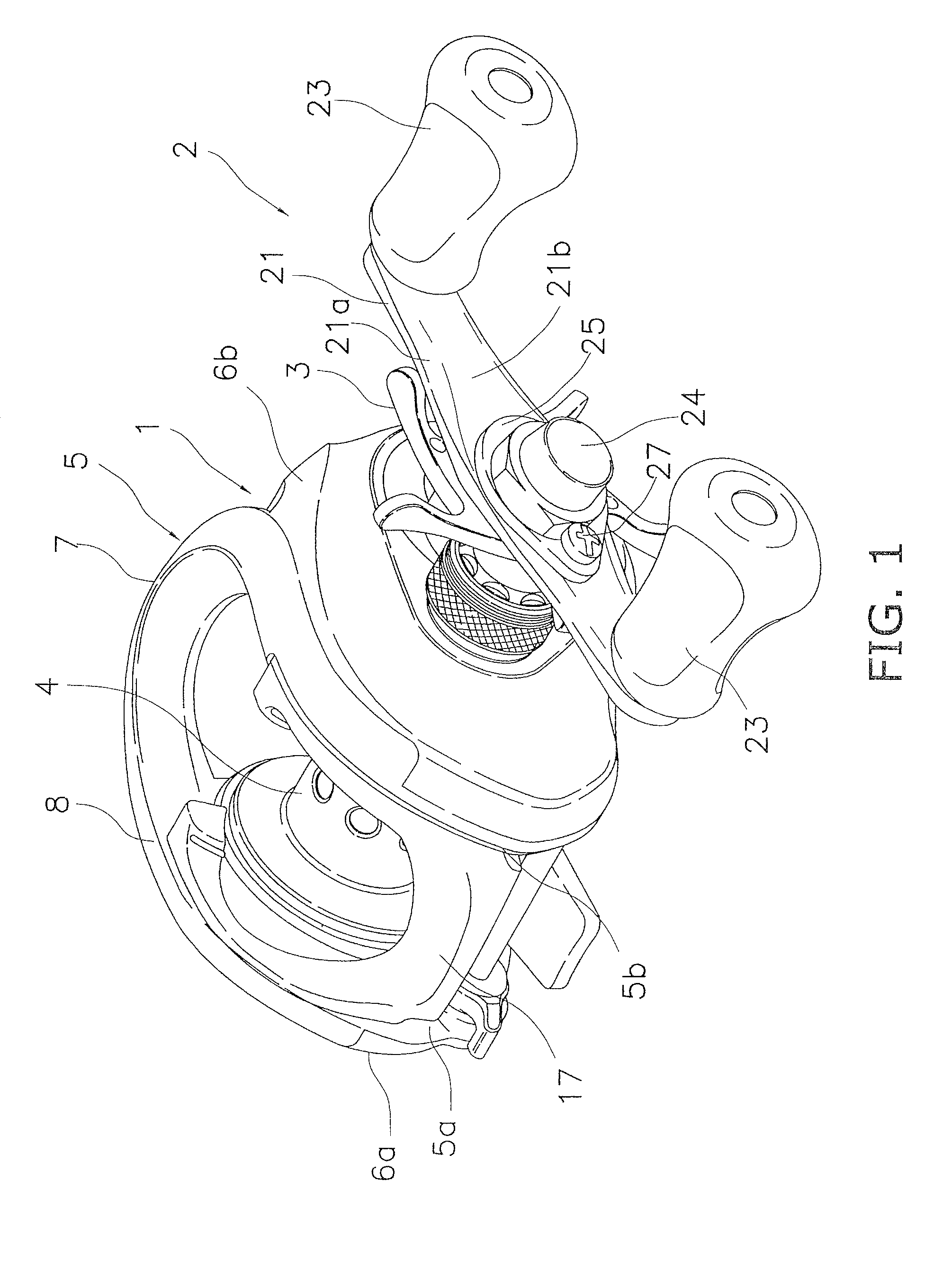
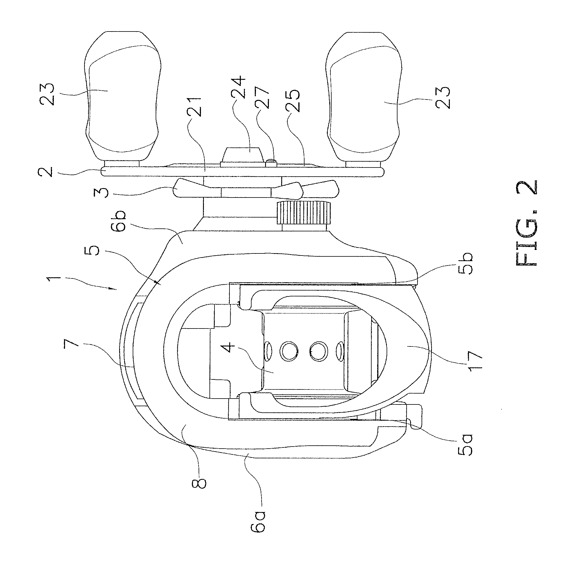
[0038]FIGS. 1 and 2 illustrate a bait-casting reel as a dual-bearing reel according to an exemplary embodiment. The dual-bearing reel includes a reel unit 1, a handle assembly 2, and a spool 4. The handle assembly 2 is a component for rotating the spool 4. The handle assembly 2 is disposed lateral to the reel unit 1. The spool 4 is a component for winding a fishing line thereon. The spool 4 is detachably attached to the interior of the reel unit 1 in a rotatable state. Further, a star drag 3 is attached to the handle assembly 2 on the same side of the reel unit 1 to which the handle assembly 2 is attached. The star drag 3 ...


PUM


Abstract

A fishing reel handle assembly has a handle arm, a knob shaft, and a handle knob. The handle arm is relatively non-rotatably attached to a distal end of the handle shaft. The knob shaft is fixed to an end of the handle arm and extends in parallel to the handle shaft. The handle knob is supported by the knob shaft to be rotatable relative to the handle arm. The handle arm includes a main body and a convexo-concave portion. The main body extends substantially perpendicular to an axial direction of the handle shaft, and is formed by laminating sheets of prepreg. The convexo-concave portion is convexly or concavely formed on at least either a front surface of the main body or a back surface of the main body. The front surface allows the handle knob to be attached thereto, the back surface disposed opposite to the front surface.

Description

CROSS-REFERENCE TO RELATED APPLICATIONS[0001]This application claims priority to Japanese Patent Application No. 2009-226044 filed on Sep. 30, 2009, the entirety of which is hereby incorporated by reference.BACKGROUND[0002]1. Field of the Invention[0003]The present invention generally relates to a handle assembly, and more specifically, to a fishing-reel handle assembly attached to a distal end of a handle shaft while being prevented from rotating relative to the handle shaft.[0004]2. Background Information[0005]Fishing reels, e.g., the spinning reels and the dual bearing reels, generally include a handle assembly attached to a distal end of a handle shaft. The handle assembly includes a handle arm, a knob shaft, and a handle knob. The handle arm is attached to the distal end of the handle shaft while being prevented from rotating relative to the handle shaft. The knob shaft is fixed to a longitudinal end of the handle arm. The handle knob is rotatably attached to the knob shaft.[00...

Claims


Application Information

Patent Timeline
Patent Type & Authority Patents(United States)
IPC IPC(8): A01K89/01
CPCA01K89/006A01K89/01A01K89/015A01K89/033G05G1/085
Inventor NIITSUMA, AKIRANAGASHIMA, HIROTAKA
Owner SHIMANO INC
Why Eureka
Try Eureka