Dryer

a dryer and dryer technology, applied in the field of dryers, can solve problems such as deterioration in the reliability of dryers

Active Publication Date: 2014-04-22
SAMSUNG ELECTRONICS CO LTD
View PDF20 Cites 10 Cited by
  • Summary
  • Abstract
  • Description
  • Claims
  • Application Information

AI Technical Summary

Benefits of technology

[0009]It is one aspect of the present disclosure to provide a dryer and a control method thereof, in which load of an object to be dried is detected and an anticipated drying time based on the detected load is accurately determined and displayed.
[0010]It is another aspect of the present disclosure to provide a dryer and a control method thereof, in which load of an object is accurately detected using a sensor which has less risk of contamination, which ensures reliable anticipation of a drying time.
[0016]The humidity sensor may enable compensation of the drying time by detecting humidity in a section in which humidity detection by the electrode sensor is not possible.

Problems solved by technology

However, since these conventional dryers function to display the remaining drying time regardless of load of an object to be dried, i.e. the amount of moisture contained in the object to be dried, there is a great difference between an actual remaining drying time and a remaining drying time displayed on the display unit, resulting in deterioration in the reliability of the dryer.

Method used


Image

  • Dryer
  • Dryer
  • Dryer

Examples


Embodiment Construction

[0028]Reference will now be made in detail to the exemplary embodiment of the present disclosure, examples of which are illustrated in the accompanying drawings, wherein like reference numerals refer to like elements throughout.

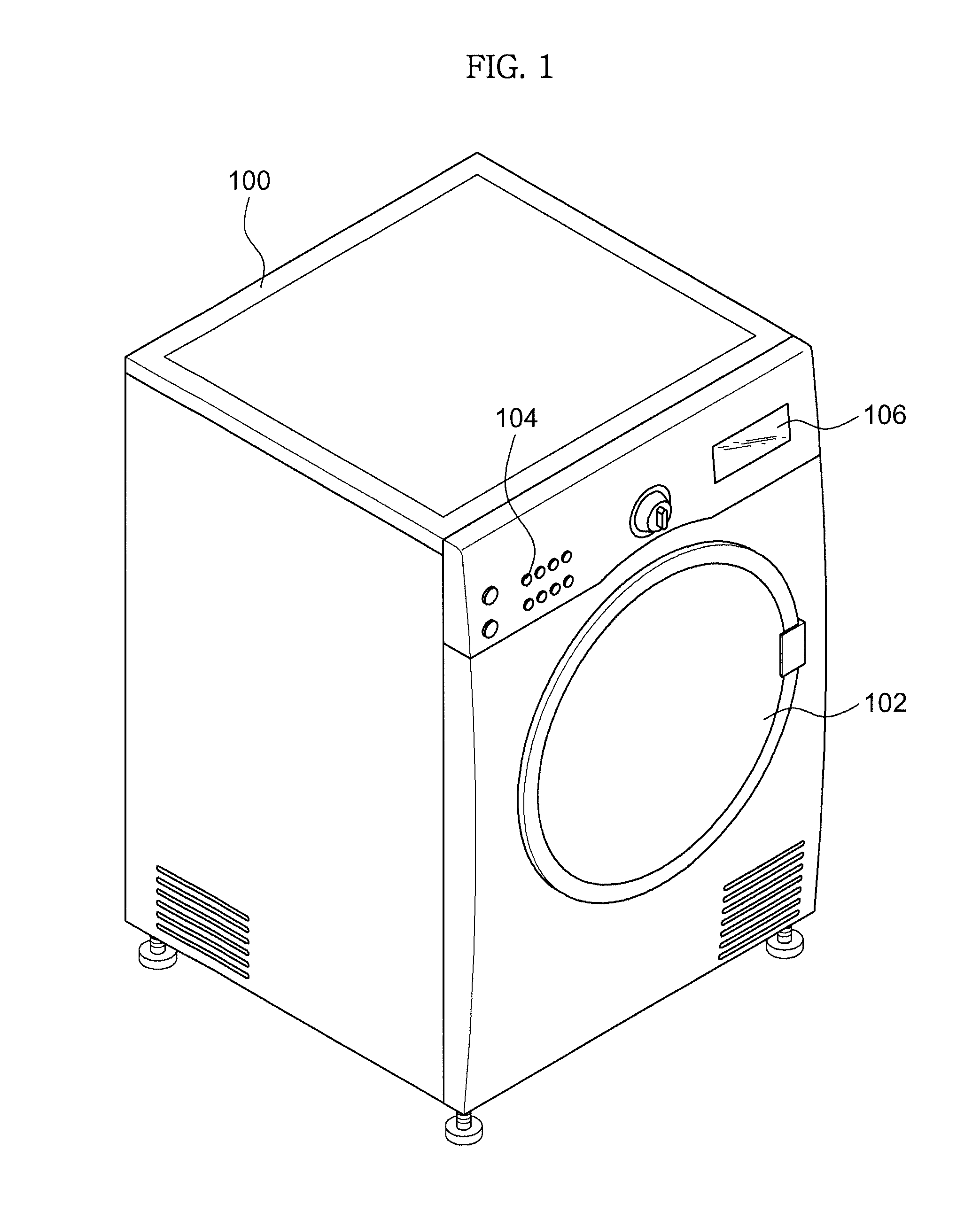
[0029]FIG. 1 is a view illustrating a dryer according to an embodiment of the present disclosure. As illustrated in FIG. 1, a door 102 is provided at a front opening of a main body 100 of the dryer, an object to be dried being put into or taken out of the dryer through the front opening. A control panel 104, which serves as an input unit, and a display 106, which serves as a display unit, are provided above the door 102 at the front side of the main body 100. The control panel 104 allows a user to input drying conditions (e.g., a desired drying level). The display 106 displays the drying conditions selected by the user or operational states of the dryer (e.g., a current temperature or an anticipated drying time) during operation of the dryer, to allow the use...


PUM


Abstract

A dryer and a control method thereof, in which load of an object to be dried is detected using a sensor which has less risk of contamination and an anticipated drying time based on the detected load is accurately determined and displayed. The dryer includes a rotatable drum to accommodate the object, a front support installed at an entrance of the drum to support the drum, a rear support installed at an opposite side of the entrance of the drum to support the drum, an exhaust hole formed in the front support, through which interior air of the drum is discharged, and a humidity sensor installed to the front support at a position adjacent to the exhaust hole, the humidity sensor being located upstream of the exhaust hole in a rotating direction of the drum to detect humidity of the air to be introduced into the exhaust hole.

Description

CROSS-REFERENCE TO RELATED APPLICATIONS[0001]This application claims the benefit of Korean Patent Application No. 10-2010-0126854, filed on Dec. 13, 2010 in the Korean Intellectual Property Office, the disclosure of which is incorporated herein by reference.BACKGROUND[0002]1. Field[0003]Embodiments of the present disclosure relate to a dryer to dry an object accommodated in a drum via circulation of air.[0004]2. Description of the Related Art[0005]In general, a dryer includes a drum in which an object to be dried is accommodated, the drum being rotated to rotate the object, and a heat source (e.g., a heater or a heat pump) to heat air. As a drying fan is rotated to move low-temperature and low-humidity air through the heat source, the low-temperature and low-humidity air is changed into high-temperature and low-humidity air by the heat source. The resulting high-temperature and low-humidity air is introduced into the drum to heat the object to be dried. Then, the high-temperature an...

Claims


Application Information

Patent Timeline
Patent Type & Authority Patents(United States)
IPC IPC(8): F26B11/02
CPCD06F2058/2819D06F2058/2829D06F2058/2896D06F2058/2883D06F58/28D06F58/04D06F34/28D06F58/38D06F2103/08D06F2103/38D06F2105/58D06F2105/56D06F58/46D06F2105/30D06F2103/34D06F34/26D06F2101/00D06F2103/32D06F58/20D06F2105/28
Inventor PARK, HEE BEOMCHANG, PHIL SOOLEE, HYUNG WOO
Owner SAMSUNG ELECTRONICS CO LTD
Why Eureka
Try Eureka