Method of manufacturing optical fiber base material and apparatus of the same

a manufacturing method and technology of optical fiber, applied in the direction of manufacturing tools, lighting and heating equipment, furniture, etc., can solve the problems of increased transmission loss of optical fiber base material, and less strength of synthetic quartz glass tube at a high temperatur

Active Publication Date: 2014-04-22
SHIN ETSU CHEM CO LTD
View PDF16 Cites 0 Cited by
  • Summary
  • Abstract
  • Description
  • Claims
  • Application Information

AI Technical Summary

Benefits of technology

[0013]The problem that the transmission loss of the optical fiber base material increases when the natural quartz glass tube is used as the furnace tube can be solved by using the synthetic quartz glass tube in place of the natural quartz glass tube. However, there is another problem that the strength of the synthetic quartz glass tube at a high temperature is less than that of the natural quartz glass tube. For example, since the synthetic quartz furnace tube does not crystallize even if it is used at a high temperature. Therefore, the synthetic quartz furnace tube softens around 1,500 degrees Celsius within processing temperatures, and the furnace tube is deformed because the pressure in the furnace tube is slightly fluctuated around ±3 kPa. This deformation may cause the furnace tube to contact and damage the porous glass base material. Meanwhile, the natural quartz furnace tube easily crystallizes as described above, and the crystallized furnace tube is not easily deformed at a high temperature.

Problems solved by technology

When a porous glass base material is dehydrated and sintered by using the natural quartz glass tube as a furnace tube, a resultant optical fiber base material has a problem that the transmission loss increases possibly caused by a little impurity contained in natural quartz.
The problem that the transmission loss of the optical fiber base material increases when the natural quartz glass tube is used as the furnace tube can be solved by using the synthetic quartz glass tube in place of the natural quartz glass tube.
However, there is another problem that the strength of the synthetic quartz glass tube at a high temperature is less than that of the natural quartz glass tube.
This deformation may cause the furnace tube to contact and damage the porous glass base material.
Meanwhile, the natural quartz furnace tube easily crystallizes as described above, and the crystallized furnace tube is not easily deformed at a high temperature.

Method used


Image

  • Method of manufacturing optical fiber base material and apparatus of the same
  • Method of manufacturing optical fiber base material and apparatus of the same
  • Method of manufacturing optical fiber base material and apparatus of the same

Examples


embodiment 1

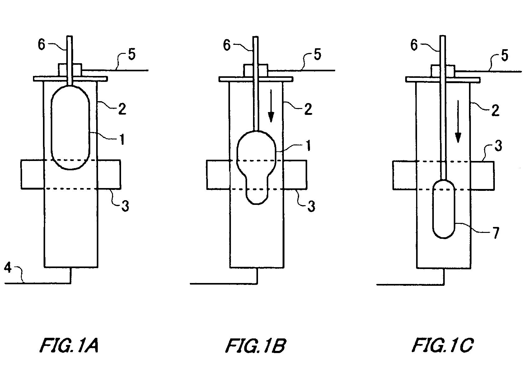
[0034]A composite tube is manufactured by: forming a soot deposit by hydrolyzing silicide such as SiCl4, (CH3)SiCL3, (CH3)2SiCL2 with oxyhydrogen flame; and jacketing, with a natural quartz tube having a thickness of 4 mm, a synthetic quartz tube having a thickness of 4 mm which is vitrified by melting with a heating furnace. For example, the synthetic quartz tube may be such as SH100 and SH120 (trade name) and the natural quartz tube may be HERALUX-E (trade name), both products are available from Shin-Etsu Quartz Products Co., Ltd.

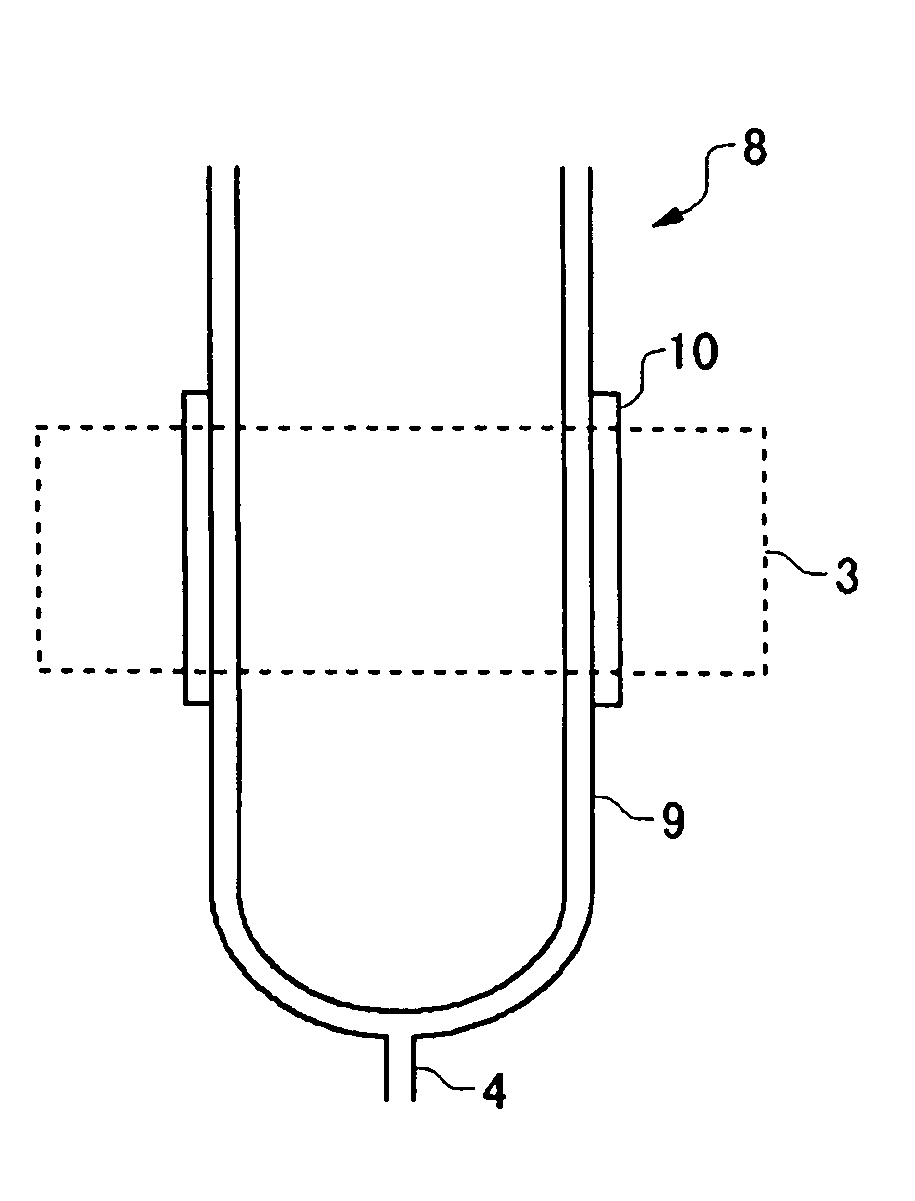
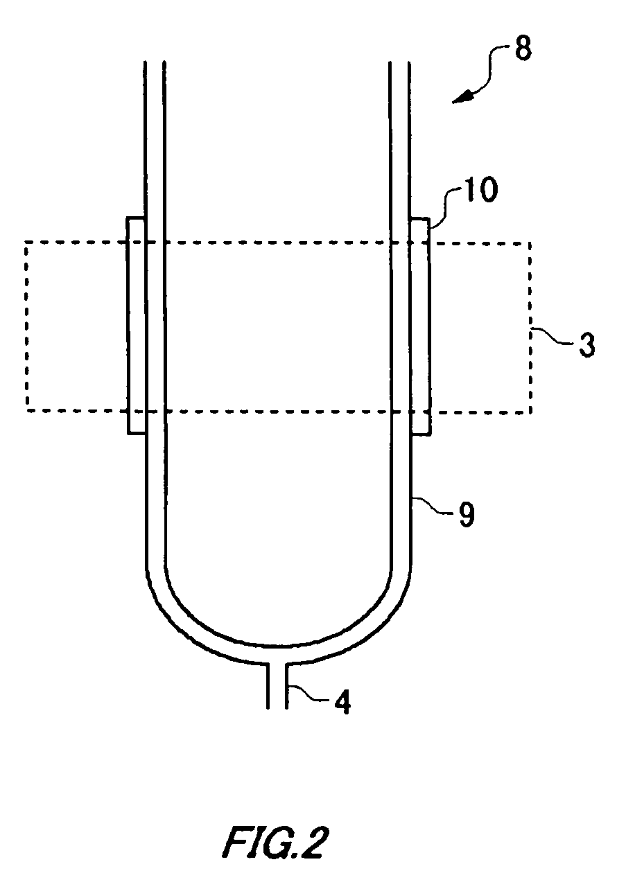
[0035]As schematically shown in FIG. 2, a composite furnace tube 8 which is formed by jacketing a synthetic quartz glass tube 9 with the natural quartz glass tube 10 sufficiently covers a heating region of an electric furnace 3 as a heat source, and the composite furnace tube 8 is mounted to the heating furnace. Here, the composite tube may be configured as an entire furnace tube, however, when a region to be heated at a high temperature is limited, the c...


PUM

PropertyMeasurementUnit
pressureaaaaaaaaaa
temperatureaaaaaaaaaa
depthaaaaaaaaaa

Abstract

A method of manufacturing an optical fiber base material includes: forming a porous glass base material by depositing glass particles; providing a vessel which employs a composite tube, the composite tube including a portion formed by jacketing a first quartz glass containing aluminum equal to or less than 0.01 ppm with a second quartz glass containing aluminum equal to or more than 15 ppm; introducing dehydration reaction gas and inert gas into the vessel; heating the jacketed portion in the vessel which contains the dehydration reaction gas and the inert gas; and inserting the porous glass base material into the heated vessel to dehydrate and sinter the porous glass base material.

Description

CROSS REFERENCE TO RELATED APPLICATION[0001]The present application is a continuation in-part application of PCT / JP2007 / 062809 filed Jun. 26, 2007, which claims priority from Japanese Patent Application No. 2006-175708 filed Jun. 26, 2006, and from Japanese Patent Application No. 2007-164421 filed Jun. 21, 2007, the contents of which are incorporated herein in their entireties by this reference.BACKGROUND[0002]1. Technical Field[0003]The present invention relates to a method of manufacturing an optical fiber base material being capable of manufacturing an optical fiber base material of high quality by so-called VAD.[0004]2. Related Art[0005]VAD is well-known as a method of manufacturing base materials for optical fibers. This method employs the following apparatus, for example.[0006]In this apparatus, glass particles produced with a core deposition burner and a cladding deposition burner disposed in a reaction chamber; and the glass particles are deposited onto a tip of a starter mo...

Claims


Application Information

Patent Timeline
Patent Type & Authority Patents(United States)
IPC IPC(8): C03B37/12
CPCC03B37/01446C03B37/0146C03B37/014C03B37/018
Inventor INOUE, DAIKOIDE, HIROYUKINAGAO, TAKAAKI
Owner SHIN ETSU CHEM CO LTD
Why Eureka
Try Eureka