Z-axis capacitive accelerometer

a capacitive accelerometer and z-axis technology, applied in the direction of speed/acceleration/shock measurement, measurement devices, instruments, etc., can solve the problems of limiting the die area efficiency of electrical sensitivity, unused sensing area having the largest signal displacement, and inability to utilize significant part of the poof mass to the far tip for sensing, etc., to achieve the effect of improving the sensitivity of acceleration measurement, increasing the average distance of the capacitance sensing pla

Active Publication Date: 2014-04-22
MEMSIC
View PDF1 Cites 8 Cited by
  • Summary
  • Abstract
  • Description
  • Claims
  • Application Information

AI Technical Summary

Benefits of technology

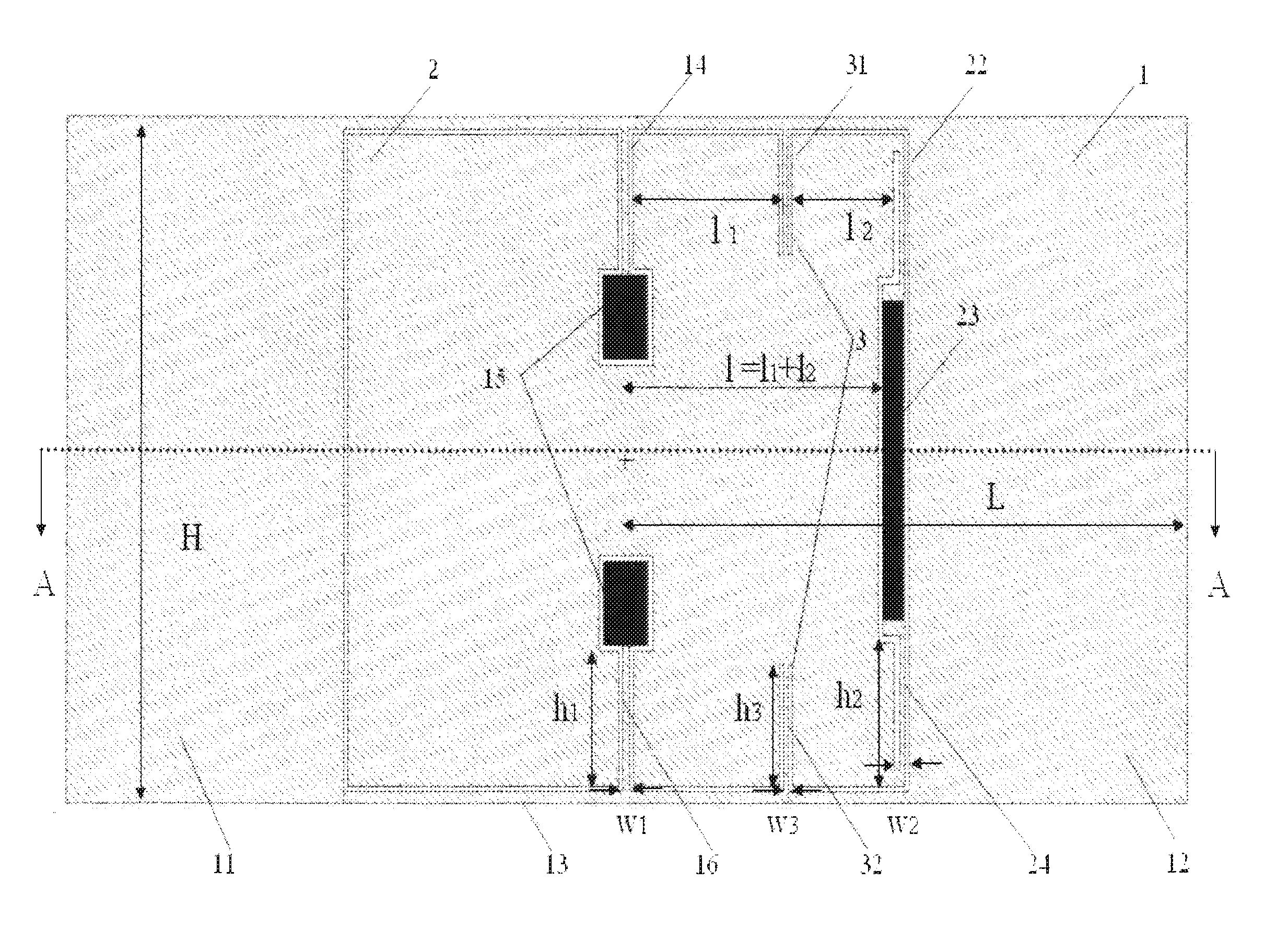
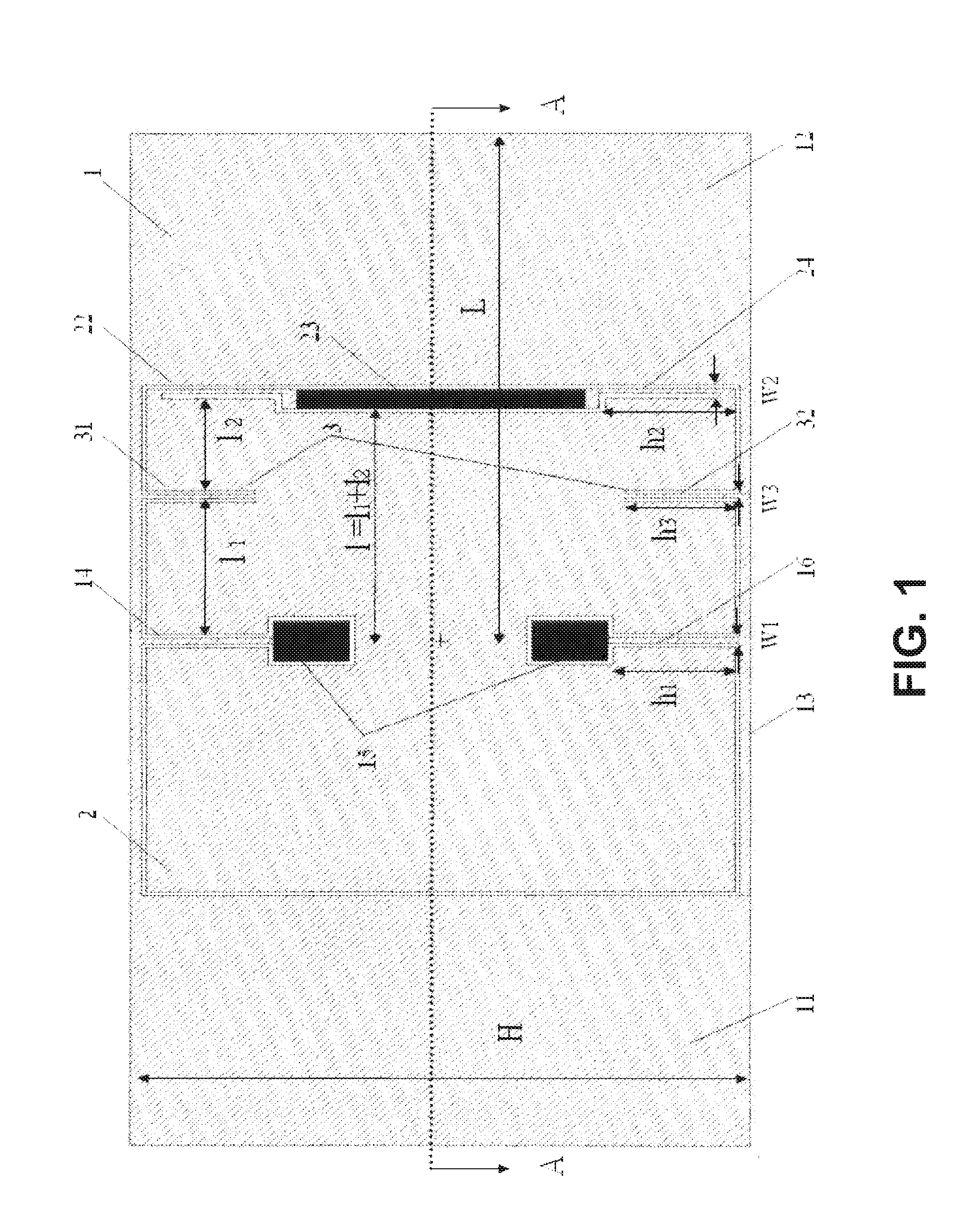
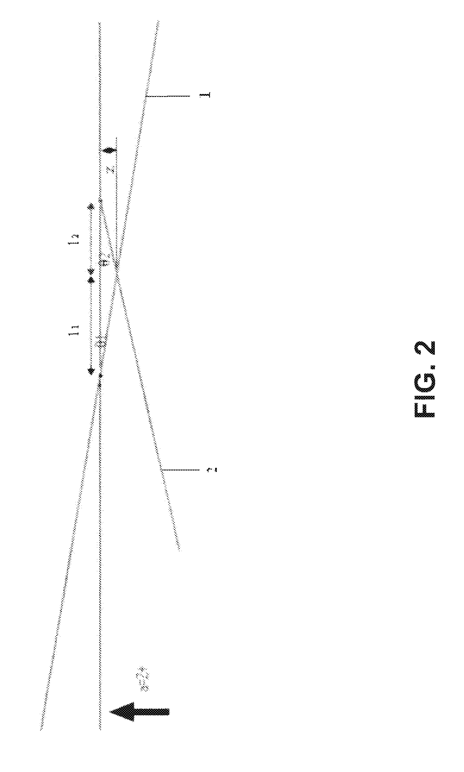
[0017]Compared with the embodiments of related art, the present invention has the following advantages. In the Z-axis capacitive accelerometer according to the present invention, a mechanical structure in which the proof mass and the capacitance sensing plate are decoupled from each other is adopted, and the differential capacitance sensing plates are placed opposite at the two sides of the rotational axis and outside the proof mass, wherein the opposite means the plates can be placed either symmetrical and nonsymmetrical to the rotational axis. The average distance of the capacitance sensing plate to the rotation axis is thus increased. Given the same angular displacement, the capacitance change of the sensing plate will be increased significantly, thereby effectively improving the sensitivity of acceleration measurement.

Problems solved by technology

However, in the conventional design of Z-axis accelerometer, a significant part of the poof mass to the far tip cannot be utilized for sensing, but only for creating imbalanced motion in response to inertial force, and the unused sensing area would have the largest signal displacement.
This substantially limits the die area efficiency for electrical sensitivity.

Method used


Image

  • Z-axis capacitive accelerometer
  • Z-axis capacitive accelerometer
  • Z-axis capacitive accelerometer

Examples


Embodiment Construction

[0022]The present invention is more particularly described in the following examples that are intended as illustrative only since numerous modifications and variations therein will be apparent to those skilled in the art. Various embodiments of the invention are now described in detail. Referring to the drawings, like numbers indicate like parts throughout the views. As used in the description herein and throughout the claims that follow, the meaning of “a,”“an,” and “the” includes plural reference unless the context clearly dictates otherwise. Also, as used in the description herein and throughout the claims that follow, the meaning of “in” includes “in” and “on” unless the context clearly dictates otherwise. Moreover, titles or subtitles may be used in the specification for the convenience of a reader, which has no influence on the scope of the invention. Additionally, some terms used in this specification are more specifically defined below.

[0023]The description will be made as t...


PUM


Abstract

A Z-axis capacitive accelerometer includes a substrate, a capacitance sensing plate, a proof mass and at least one pair of spring beams. The capacitance sensing plate includes two symmetrical sense areas to create differential capacitive measurement. A decoupling structure separates the proof mass and the capacitance sensing plate and their rotational motions from each other. In the proposed Z axis capacitive accelerometer, the distance of the capacitance sensing plate relative to its rotation axis is considerably increased, thereby effectively enhancing the sensitivity when measuring the Z-axis acceleration.

Description

CROSS-REFERENCE TO RELATED APPLICATION[0001]This application claims priority of Chinese Patent Application No. 201010552669.3, filed on Nov. 19, 2010, entitled “Z-Axis Capacitive Accelerometer” by Leyue JIANG, Hanqin ZHOU, and Yang ZHAO, the disclosure of which is incorporated herein by reference in its entirety.FIELD OF THE INVENTION[0002]The present invention relates to a Micro-Electro-Mechanical System (MEMS) capacitive accelerometer, and more particularly to a capacitive accelerometer for measuring the Z-axis (out-of-plane) acceleration.BACKGROUND OF THE INVENTION[0003]With the development of micro-electro-mechanical system (MEMS) technology, micro-size, reliable, and low-cost silicon accelerometers have been in volume production and widely adopted in automotive, consumer electronics, and industrial applications.[0004]The operation principle of the differential capacitive micro-accelerometer is as follows. A proof mass is suspended above the substrate by spring beams / tethers and...

Claims


Application Information

Patent Timeline
Patent Type & Authority Patents(United States)
IPC IPC(8): G01P15/125
CPCG01P15/125G01P2015/0831G01P2015/0837
Inventor JIANG, LEYUEZHOU, HANQINZHAO, YANG
Owner MEMSIC
Why Eureka
Try Eureka