
Slide board for use on snow

a technology for slide boards and snow, which is applied in the direction of skis, sport apparatus, skates, etc., can solve the problems of negative consequences on the behavior of the board, the effect of reducing the overall cross-section and enhancing the effect of improvemen

Inactive Publication Date: 2014-04-22
SKIS ROSSIGNOL
View PDF15 Cites 0 Cited by
  • Summary
  • Abstract
  • Description
  • Claims
  • Application Information

AI Technical Summary

Benefits of technology

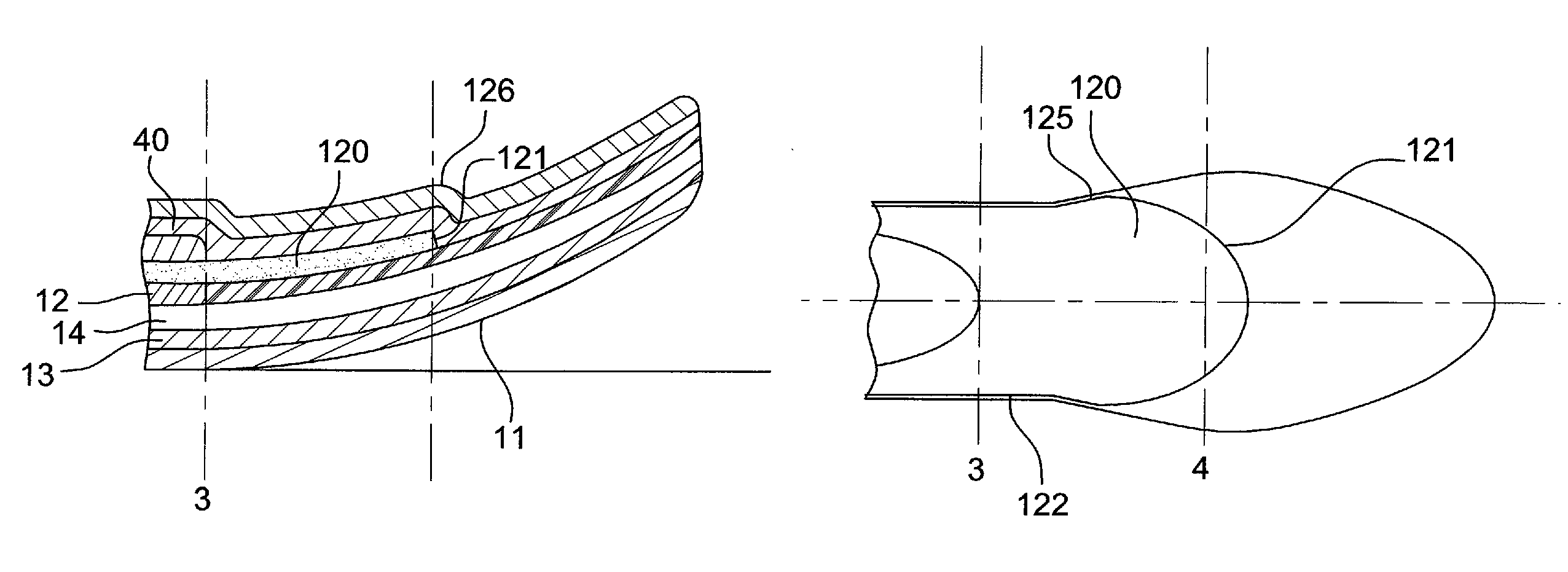
The patent describes a ski design that optimizes the impact of the reinforcement layer on the flexural and torsional rigidity of the tip. This is achieved by shaping the end of the reinforcement layer so that it does not take up the entire surface of the tip, and instead has a controlled proportion of the tip to minimize the impact on the stiffness of the tip. This design allows the ski to have improved edge hold and catch when turning. Additionally, a second mechanical reinforcement layer or layers can be used to further enhance the progressive nature of the mechanical properties of the ski.

Problems solved by technology

However, this tip (or indeed heel) widening, dictated by considerations of lift, may have negative consequences on the behavior of the board.
Indeed, conventionally, a ski comprises an internal structure consisting of a core which intrinsically lacks any high strength mechanical properties, but which allows separation from the neutral fiber of the mechanical enforcement layers.
This construction does however have one major drawback in the case of skis for which the point of maximum width is located forward from the front contact line.
The clear advantage in terms of lift on powder snows therefore turns into a disadvantage in respect of harder snows, since, because of its rigidity, the tip may alter the required deformation particularly when engaged on a turn.
This solution is not really satisfactory, in that it slightly reduces the torsional value of the tip and it has almost no impact on its flexural rigidity.
Additionally and above all, the mechanical complexity of such a solution is a significant source of fragility for the ski, making it very difficult to use.

Method used


Image

  • Slide board for use on snow
  • Slide board for use on snow
  • Slide board for use on snow

Examples


Embodiment Construction

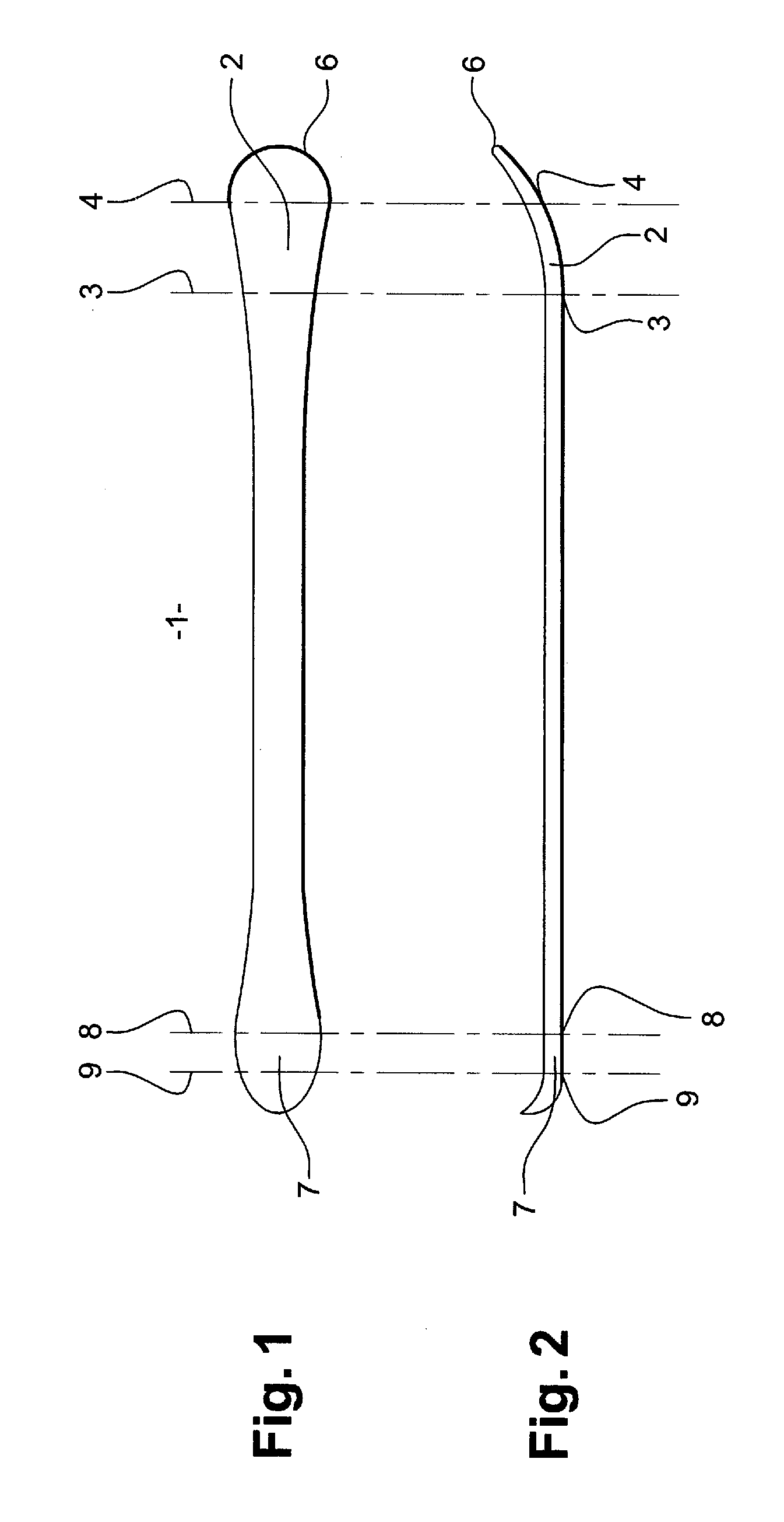
[0040]As already mentioned, the invention relates to the family of slide boards and more particularly downhill skis which have a tip and / or a heel of large surface area. To be more precise, and as shown in FIG. 1, the ski 1 has a tip 2 defined forward from the front contact line 3, the ski being set flat. Forward from this front contact line 3, the tip 2 has a width which is maximum at the so-called “maximum width” line 4.

[0041]Symmetrically, although in different proportions as regards the dimensions, the board upturn at the rear of the ski, namely the heel 7, is defined to the rear of the rear contact line 8. It may have a maximum width line 9 also located to the rear of the rear contact line 8.

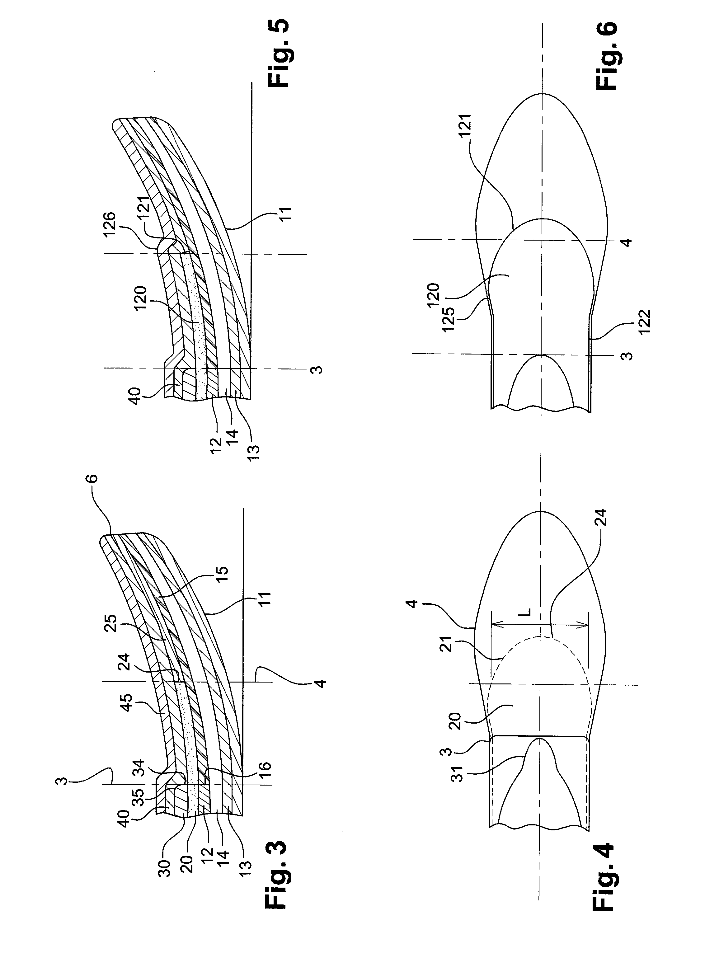
[0042]To be more precise, and in an embodiment example shown in FIG. 3, the tip 2 is implemented by assembling the following layers.

[0043]First of all, the sole 11 forms the lower layer, which comes into direct contact with the snow. The board also includes a core 12, which may be a pre-mac...


PUM


Abstract

A slide board for use on snow has a point of maximum width located beyond the contact line. The board includes a core extending over the greater part of the board, and a plurality of mechanical reinforcement layers lying directly or indirectly on the core, extending inside the board upturn beyond the contact line. The reinforcement layers are inclusive of that part of the board comprising the longitudinal axis. At least one of the reinforcement layers has an extreme longitudinal point offset transversely relative to the longitudinal axis of the board and, in a zone defined between the contact line and the point of maximum width, the reinforcement layer has an overall cross-section which decreases between the contact line and the point of maximum width. The reinforcement layers have extreme longitudinal points offset longitudinally relative to each other.

Description

CROSS REFERENCE TO RELATED APPLICATIONS[0001]This application claims priority under 35 U.S.C. §119 from French Patent Application No. 0954668 filed on Jul. 6, 2009 in the French Patent Office, and French Patent Application No. 0956903 filed on Oct. 2, 2009 in the French Patent Office, the entire disclosure of which is incorporated herein by reference.FIELD OF INVENTION[0002]The invention relates to the field of the manufacture of slide boards for use on snow, and more particularly downhill skis. It relates more specifically to skis whereof the board upturn, in other words the tip or heel, is widened to improve board lift. It is aimed more specifically at an architecture of the internal structure of such boards, intended to improve the behavior and facilitate the handling thereof.[0003]In the remainder of the description, the invention may be described in relation more specifically to the front end upturn, in other words the tip, but it goes without saying that the same features may ...

Claims


Application Information

Patent Timeline
Patent Type & Authority Patents(United States)
IPC IPC(8): A63C5/14
CPCA63C5/0405A63C5/0411A63C5/052A63C5/006
Inventor DUTAUT, JEAN-LUCBILLON, PIERREPUGET, NICOLAS
Owner SKIS ROSSIGNOL
Learn More