Graded index birefringent component and manufacturing method thereof

a technology of index birefringent and component, applied in the field of optical components, can solve the problems of degrading the alignment properties degrading the optical performance, and affecting the quality of liquid crystal materials, and achieve the effect of minimizing the vignetting on the other sid

Active Publication Date: 2014-04-22
AU OPTRONICS CORP
View PDF22 Cites 2 Cited by
  • Summary
  • Abstract
  • Description
  • Claims
  • Application Information

AI Technical Summary

Benefits of technology

[0022]The foregoing embodiments of the present invention have at least one of the following advantages over the known prior art.
[0023](1) A stack of a surface relief birefringent element and a cured liquid crystal layer can conveniently be formed.
[0024](2) The surface relief birefringent element and the cured liquid crystal layer are in intimate contact, so that off-axis vignetting is minimized.
[0026](4) A liquid crystal material is not used to capillary fill and can be coated onto the surface relief birefringent element in a very short timescale over large areas compared to capillary or vacuum filling. Such graded index birefringent component can thus be made so that the liquid crystal material is not prone to premature cure. Further, the liquid crystal material does not have to be vacuum filled or cured in a nitrogen blanket, thus reducing cost and complexity of equipment.

Problems solved by technology

Such a filling process has a number of difficulties.
However, these lenses may be susceptible to blockage, so that they do not fill uniformly, creating bubbles which degrade optical performance.
This can cause regions of strain in the cured liquid crystal material, degrading alignment properties of the liquid crystal material near the bubbles.
However, such an approach disadvantageously uses more material and so increases cost.
Further, the uniformity of the thickness of additional material can be difficult to maintain, so the final device may not be flat, which may cause non-uniform optical output, for example, in an autostereoscopic display system.
Vacuum equipment is disadvantageously expensive, and the high levels of vacuum used for vacuum filling may not be compatible with the lens polymer materials.
To reduce thickness after fabrication, it may be possible to remove the substrate 8 from the cured liquid crystal material 12, but if this is glass, it may be prone to cracking.
The surface energies of the interfaces between the cured liquid crystal material 12 and the alignment layers 6 and 10 may be similar, so that delamination may take place off either surface, therefore resulting in unreliability of delamination release.
Further, the addition of alignment layer 10 adds cost to the processing method.
However, this may also increase the adhesion to the alignment layer 10, and thus reduce the reliability of delamination at the planar interface between the liquid crystal material 12 and the alignment layer 10.
Further, the filling process can take some hours, particularly for a large cell required for large displays or for motherglass processing methods.
Liquid crystal polymer materials may be liable to unwanted thermal cure prior to cure by, for example, UV radiation.
This means that they are difficult to use reliably in processes with prolonged process time.
Premature cure may result in regions of non-uniform liquid crystal alignment and filling errors.
Surface relief birefringent elements such as shown in FIG. 1 are difficult to cut after processing in motherglass form.
If the prior art process were applied to the coating of surface relief birefringent elements with a curable liquid crystal polymer material, a number of difficulties would arise.
Further, the flow of the drying material on the substrate 2 may not deliver a flat surface due to differential drying properties across the width of the substrate 2.
In structures with a single alignment layer, a precise twist cannot be achieved as there is no upper surface to define an alignment.
Such a structure will result in reduced optical quality.
Therefore, an additional protective cover may need to be added, further adding to the cost of the elements.
Further, the choice of refractive indices, particularly for curable liquid crystal materials may be limited.
Such an arrangement has a high thickness, particularly due to the isotropic polymer layer 4 and the substrate 2 and requires alignment of the two respective surface relief birefringent elements 50 and 60 thus having an increased cost.
Such an arrangement has even greater thickness and cost.
Thus, it is difficult to significantly increase the optical power using surface relief birefringent elements while maintaining image quality and minimizing cost.

Method used


Image

  • Graded index birefringent component and manufacturing method thereof
  • Graded index birefringent component and manufacturing method thereof
  • Graded index birefringent component and manufacturing method thereof

Examples


Embodiment Construction

[0038]In the following detailed description, for purposes of explanation, numerous specific details are set forth in order to provide a thorough understanding of the disclosed embodiments. It will be apparent, however, that one or more embodiments may be practiced without these specific details. In other instances, well-known structures and devices are schematically depicted in order to simplify the drawings.

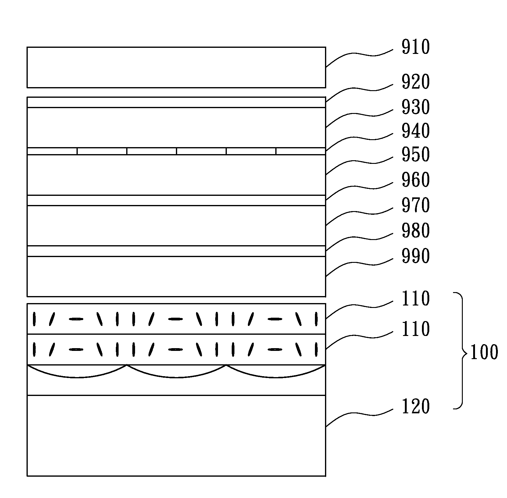
[0039]FIG. 8 shows a graded index birefringent component 100 according to one embodiment of the present invention. The graded index birefringent component 100 includes at least one liquid crystal layer 110. The liquid crystal layer 110 has a plurality of lens segments 112. Each of the lens segments 112 has a plurality of liquid crystal molecules 113 therein, wherein the orientation of the liquid crystal molecules 113 varies across each lens segment 112 of the liquid crystal layer 110.

[0040]Specifically, the liquid crystal molecules 113 in the edge of each lens segment 112 of the...


PUM

PropertyMeasurementUnit
thicknessaaaaaaaaaa
thicknessaaaaaaaaaa
thicknessaaaaaaaaaa

Abstract

A graded index birefringent component is described and shown with at least one liquid crystal layer having a plurality of lens segments, wherein the orientation of the liquid crystal molecules varies across each lens segment of the liquid crystal layer.

Description

RELATED APPLICATIONS[0001]This application claims priority to UK Application Serial Number 1015958.0, filed Sep. 22, 2010, which is herein incorporated by reference.BACKGROUND[0002]1. Technical Field[0003]The present disclosure relates to optical components. More particularly, the present disclosure relates to graded index birefringent components.[0004]2. Description of Related Art[0005]Surface relief birefringent elements are described, for example, in WO-03 / 015424 and WO-2005 / 006056. A surface relief birefringent element is formed from a surface relief interface between an isotropic layer and a birefringent layer. Light of a first linear polarization state passing through the surface relief birefringent element sees a first refractive index step at the surface relief interface between the isotropic layer and the birefringent layer, whereas light of a second orthogonal linear polarization state sees a second, different refractive index step at the surface relief interface.[0006]Sur...

Claims


Application Information

Patent Timeline
Patent Type & Authority Patents(United States)
IPC IPC(8): G02F1/1337G02F1/1335
CPCG02B27/26H04N13/0404H04N13/0454G02B3/0006G02B5/3016H04N2213/001G02B30/25H04N13/305H04N13/359G02B30/27
Inventor HARROLD, JONATHANWOODGATE, GRAHAM JOHNCHEN, CHAO-YUAN
Owner AU OPTRONICS CORP
Why Eureka
Try Eureka