Method of and apparatus for carrying out acoustic well logging

a well and acoustic technology, applied in seismology, geological measurements, instruments, etc., can solve problems such as inability to fit sigmoid function, method is likely to be sensitive to noise with high uncertainty, and real-world data may not be amenable to sigmoid function fit,

Active Publication Date: 2022-06-07
REEVES WIRELINE TECH
View PDF27 Cites 0 Cited by
  • Summary
  • Abstract
  • Description
  • Claims
  • Application Information

AI Technical Summary

Benefits of technology

[0040]The method of the present disclosure furthermore avoids the need for an iterative approach as proposed in US 2015 / 0301213. As a result, the method of the present disclosure may be operated in a very short timescale, thereby making it highly suitable for e.g. LWD situations, and other occasions when it is required for slowness calculations to be completed at high speed.
[0042]The method of the present disclosure, moreover, avoids the need to forward-model at every depth, during logging operations, a large number of possible synthetic dispersion curves and iteratively seeking to select the best-matching synthetic curve to the field slowness data. Instead, the use of synthetic dispersion curves is limited only to the training of the neural net. This saves considerably on computing time e.g. in field situations.
[0046]In one preferred embodiment of the present disclosure, the plurality of inversion depths of the well in respect of which the steps are carried out corresponds to a plurality of logging depths of the well at which logging of data occurs or has occurred in a one to one relationship. In such a case there is no need at all for the calculation of an STC shear slowness as in the prior art, or for the determination of an STC correction. This means that considerable processing time can be saved, with concomitant advantages.
[0053]This optional step addresses the possibility that peak picking may not guarantee continuity across the frequency range needed to characterize the dispersion curve. A benefit of constraining the picked peaks as aforesaid is that this takes account of the absence of high frequencies as is typical in slow formations; and also cases in which high and low frequencies are present (as is typical of fast formations). Furthermore the use of the smoothing technique is advantageous in dealing with noisy data.
[0055]As explained, the choice of implementation of the neural net results in the direct calculation of slowness, without any need for iterative processing or selection of slowness curves from a database or other set of forward modelled curves.
[0058]It is necessary to avoid the danger of inadvertently basing the calculation of slowness on an alias, and to this end the method of the present disclosure preferably includes the step of (j) using a mask to isolate a region of the field slowness-frequency-semblance map of interest in order to eliminate the risk of picking of coherence peaks derived from aliases and / or other unwanted modes in the field slowness-frequency-semblance map. In preferred embodiments of the present disclosure the method includes the step of (k) selecting the position of the mask based on a preceding field dispersion curve.

Problems solved by technology

This method is likely to be sensitive to noise with high uncertainty.
In practice, however, real-world data may not be amenable to a sigmoid-function fit.
In particular, dispersion curves are not always well-defined, symmetric sigmoids or hyperbolic tangents with a well-defined inflexion point, particularly in slow formation cases.
Although the method seems valid it is not cost-effective as doing a least squares fit between synthetic waveforms and field waveforms (with noise) is problematic.
The foregoing methods in various ways either are believed to be computationally inefficient, or slow to implement, or fail to provide accurate results in which users can have confidence.

Method used


Image

  • Method of and apparatus for carrying out acoustic well logging
  • Method of and apparatus for carrying out acoustic well logging
  • Method of and apparatus for carrying out acoustic well logging

Examples


Embodiment Construction

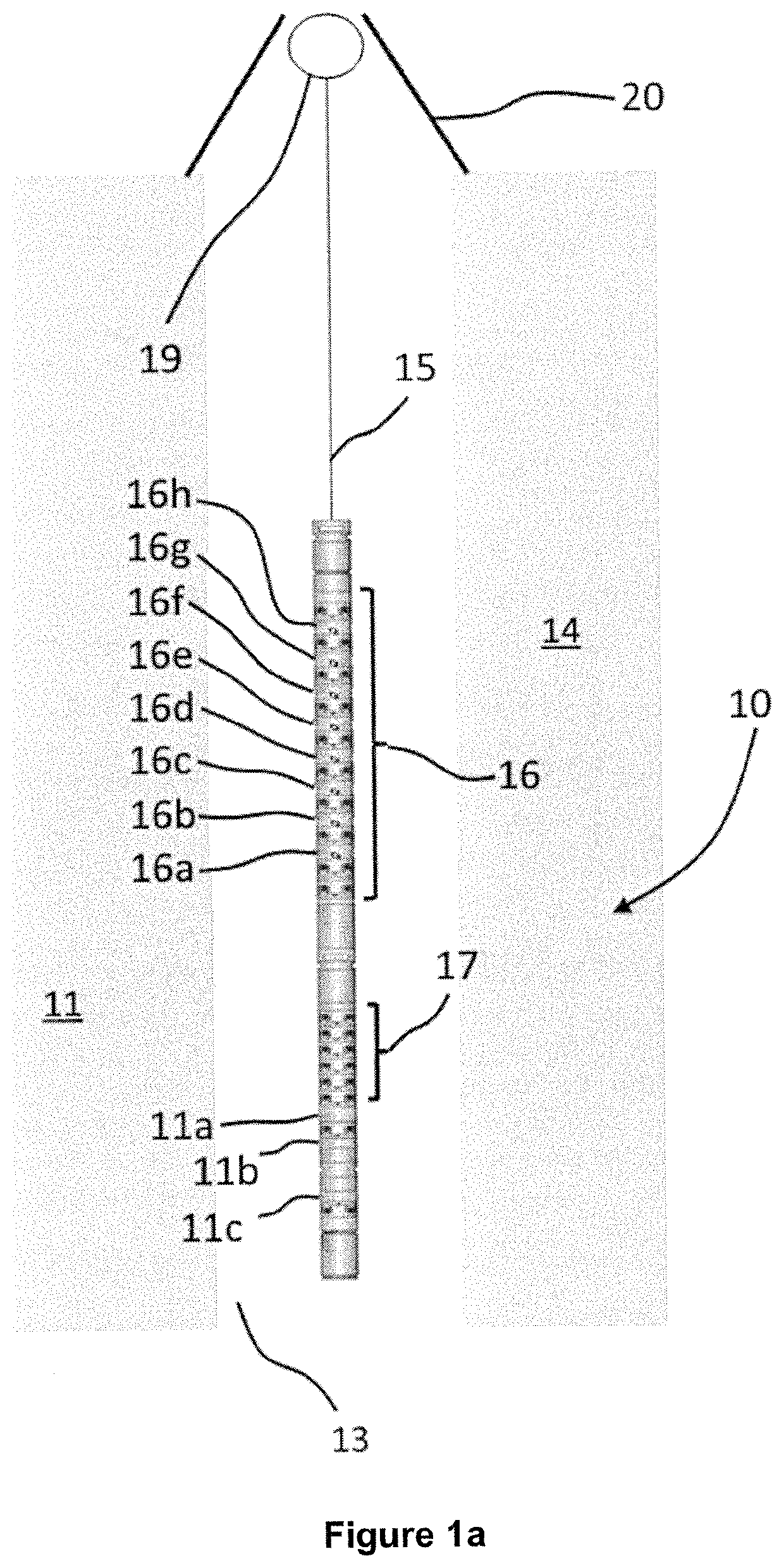
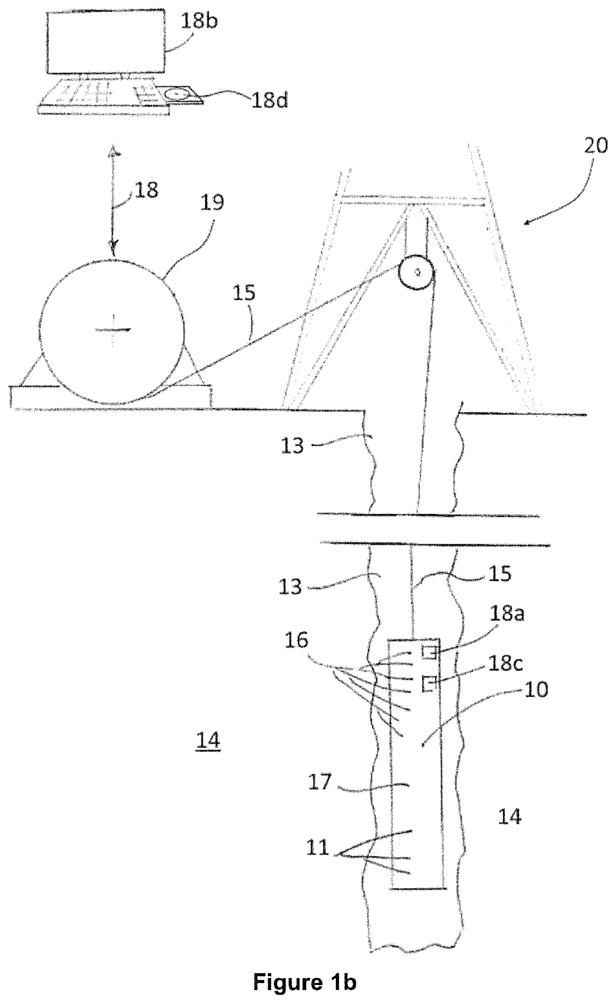
[0085]FIG. 1a illustrates one form of modern acoustic logging tool 10. Logging tool 10 includes in the illustrated embodiment three acoustic sources 11a, 11b, 11c secured towards the in-use downhole end of the elongate, cylindrical tool 10. The acoustic sources are respectively a monopole source 11a and X- and Y-axis dipole sources 11b, 11c.

[0086]The logging tool 10 also includes a series of receivers secured in a linear array 16. The receiver array 16 is spaced along the tool / sonde 10 from the sources 11a, 11b, 11c and is isolated from them by way of an acoustic isolator section 17. The isolator section 17 is intended to ensure that energy generated in the sources 11a, 11b, 11c does not contaminate the outputs of the receivers forming the array 16 by way of direct propagation via the material of the tool 10.

[0087]As is apparent from FIG. 1a, the receivers of the linear array 16 are spaced at intervals along a length of the logging tool. In the non-limiting arrangement shown in FIG...


PUM


Abstract

In acoustic well logging, for each inversion depths of a well at which logging of data occurs, acoustic log signals representative of waveforms received at acoustic receivers are processed in a frequency domain to derive field dispersion curve(s). A neural net is operated to generate formation shear slowness value(s) from the curve(s), and resulting signal(s) indicative of shear slowness values are saved, transmitted, plotted, printed or processed. An apparatus for carrying out the method includes a logging tool having at least one activatable acoustic wave source; spaced and acoustically isolated therefrom in the logging tool an array of acoustic detectors that on the detection of acoustic wave energy generate electrical or electronic log signal(s) characteristic of acoustic energy waves detected by the acoustic detector(s); and at least one processing device associated with or forming part of the logging tool for processing the log signal(s).

Description

FIELD OF THE DISCLOSURE[0001]The subject matter of the present disclosure relates to an improved method of and apparatus for carrying out acoustic well loggingBACKGROUND OF THE DISCLOSURE[0002]As is well known, prospecting for minerals of commercial or other value (including but not limited to hydrocarbons in liquid or gaseous form; water e.g. in aquifers; and various solids used e.g. as fuels, ores or in manufacturing) is economically and technically an important and challenging activity. For various reasons those wishing to extract minerals and other substances as aforesaid from below the surface of the ground or beneath the floor of an ocean need to acquire as much information as possible about both the potential commercial worth of the minerals in a geological formation and also any difficulties that may arise in the extraction of the minerals to surface locations at which they may be used.[0003]For this reason, over many decades techniques of logging of subterranean formations ...

Claims


Application Information

Patent Timeline
Patent Type & Authority Patents(United States)
IPC IPC(8): G01V1/00G01V1/48G01V1/46G01V1/30
CPCG01V1/48G01V1/305G01V1/46G01V2210/32G01V2210/582G01N3/02G01V1/50G01V2210/6242G01V2210/6222G01V2210/47
Inventor ASSOUS, SAIDELKINGTON, PETER ADRIAN SPENCERTUDGE, JOANNEWHETTON, JAMES ANTHONY
Owner REEVES WIRELINE TECH
Why Eureka
Try Eureka