Active noise cancellation apparatus

a technology of active noise and noise cancellation, which is applied in the direction of position/direction control, special data processing applications, animal undercarriages, etc., can solve the problems of increasing the overall apparatus cost, increasing the cost of the overall apparatus, and inevitably poor responsiveness of the control of the high frequency rang

Active Publication Date: 2014-04-22
SUMITOMO RIKO CO LTD
View PDF10 Cites 2 Cited by
  • Summary
  • Abstract
  • Description
  • Claims
  • Application Information

AI Technical Summary

Benefits of technology

[0097]The reference signal detector 62 is mounted on the knuckle 41 just like in Example 1. The error signal detector 163 is mounted on a portion of the suspension member 48 on which the vibration generator 161 is attached. That is to say, the error signal detector 163 is mounted on a side of the floor panel 21 in the vibration transmission path from the wheel 10 to the floor panel 21. Here, the viscoelastic members are present between the knuckle 41 and the suspension member 48 as mentioned before. Therefore, the error signal detector 163 detects vibration of the member which vibrates with a time delay from vibration of the knuckle 41. In this example, vibration to be transmitted to the floor panel 21 by way of the suspension member 48 can be reduced. Therefore, the aforementioned vibration of the floor panel 21 can be more reliably reduced. In addition, the advantageous effects mentioned in Example 1 can be exhibited.

Problems solved by technology

Besides, in some cases, road noise is generated by vibration of plate-like interior parts, such as a windshield, a rear window and door panels, other than the floor panel.
These upgrades lead to an increase in costs of the overall apparatus.
Even if a high frequency range can be controlled, the control of the high frequency range inevitably has poor responsiveness when compared to that of a low frequency range.
Therefore, after all, noise reduction performance degrades in the high frequency range.
Moreover, since vibration of the floor panel or other plate-like interior parts near the first resonance frequency is great, the vibration generator needs to generate vibration having an amplitude capable of suppressing this great vibration.
This leads to an increase in the size of the vibration generator.

Method used


Image

  • Active noise cancellation apparatus
  • Active noise cancellation apparatus
  • Active noise cancellation apparatus

Examples


example 1

Outline of Active Noise Cancellation Apparatus

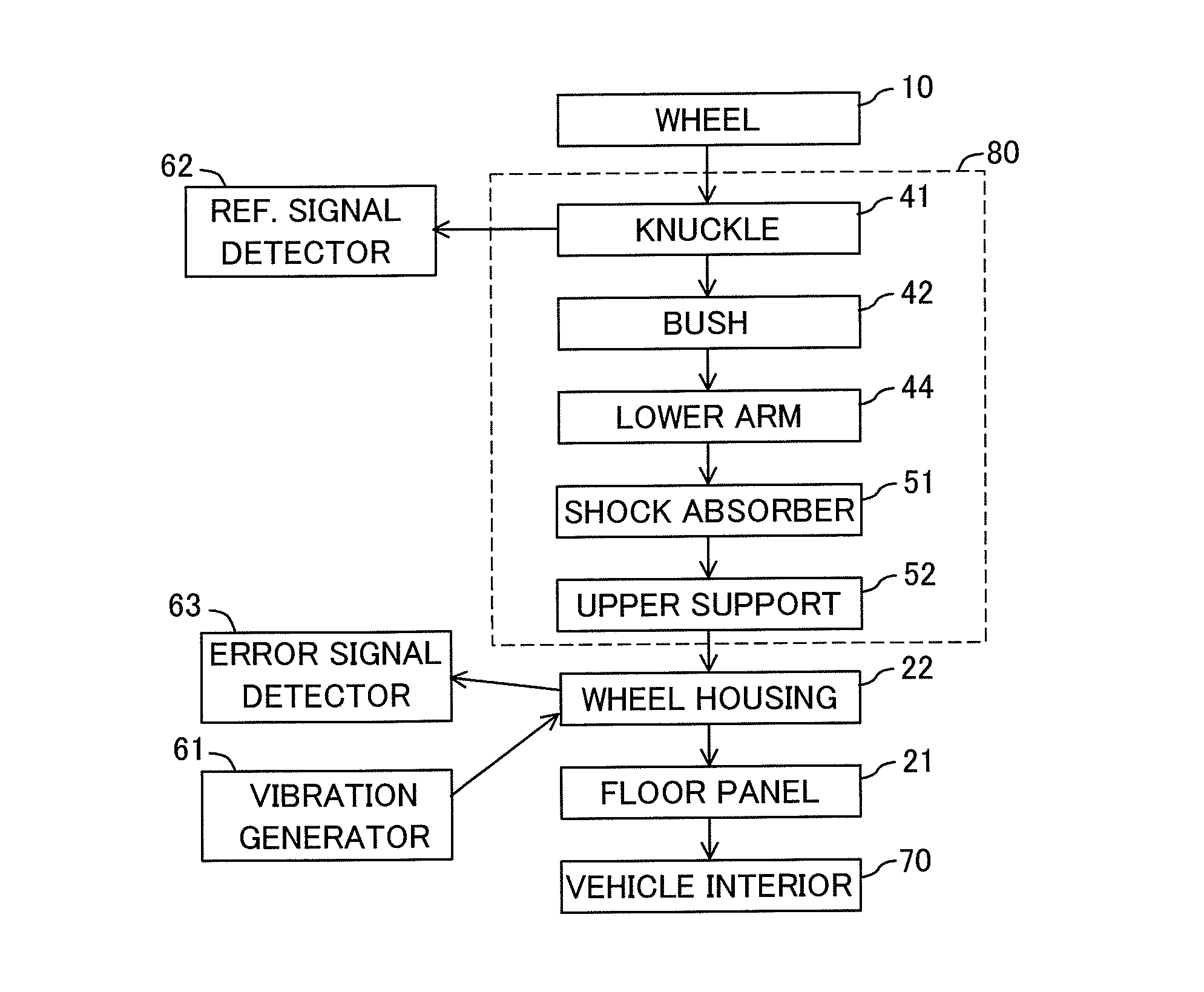
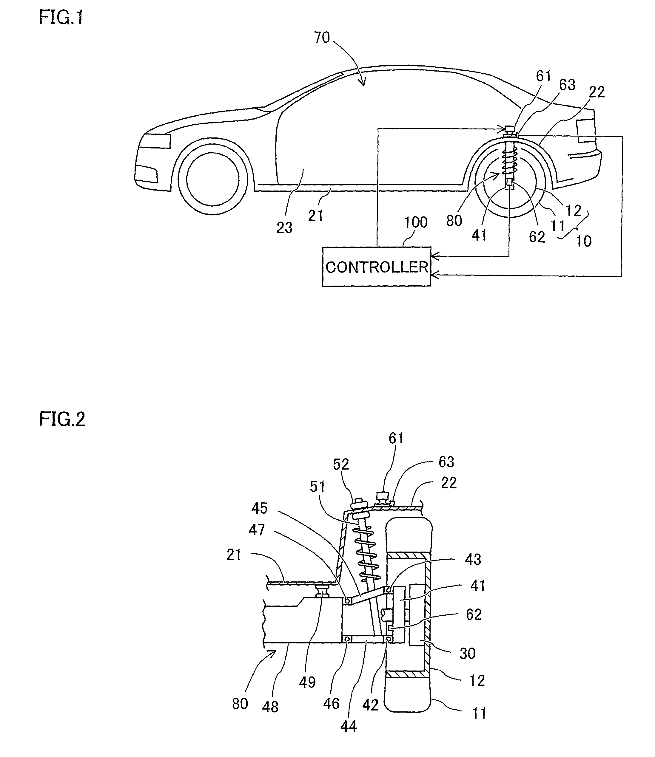
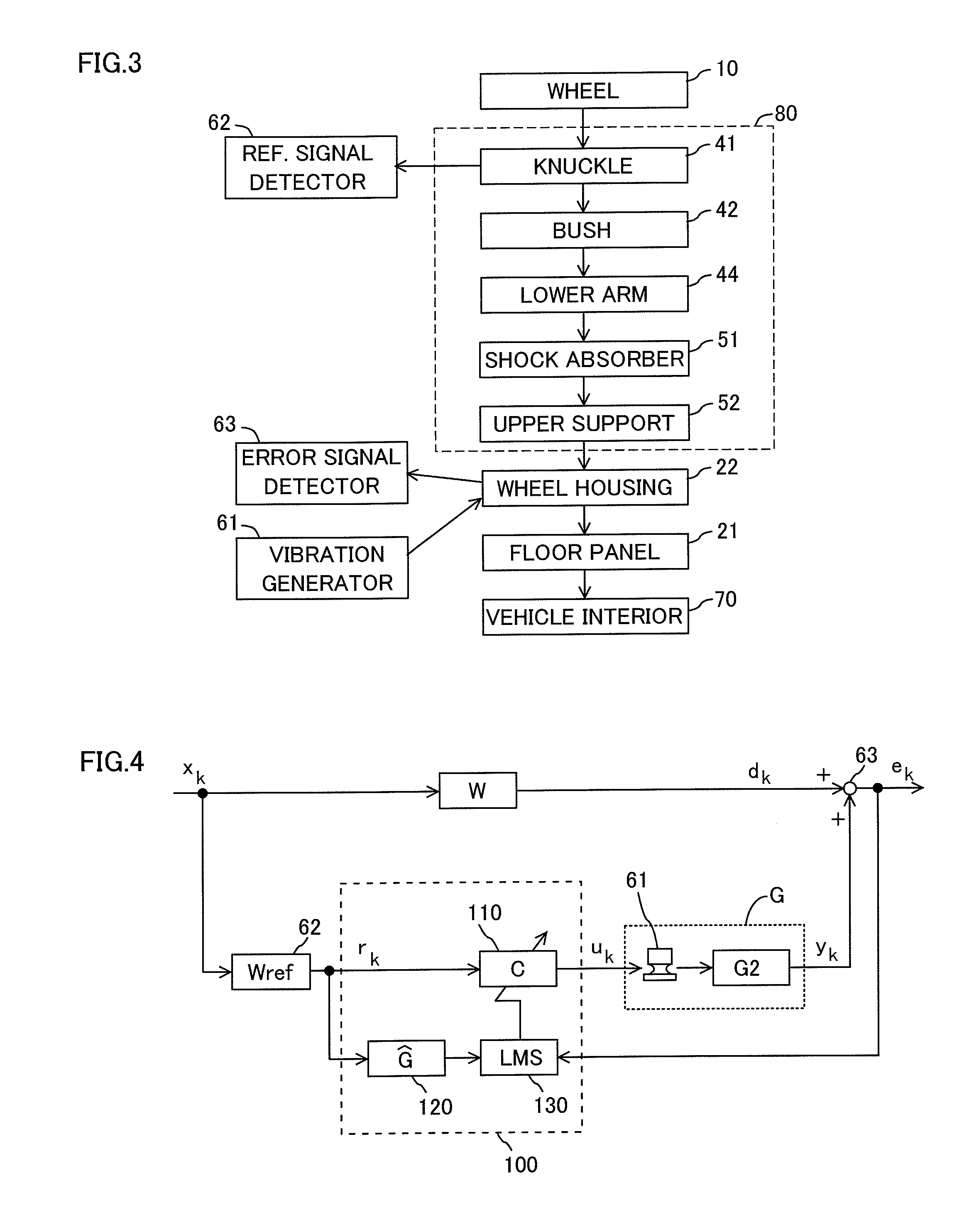
[0053]An active noise cancellation apparatus is an apparatus applied to a vehicle such as an automobile and reducing road noise. The active noise cancellation apparatus reduces road noise not by generating control noise from a speaker in a vehicle interior. As shown in FIG. 1, road noise is generated in a vehicle interior 70 by vibration of a floor panel 21, as a result of road surface vibration caused by moving of a vehicle being transmitted from a wheel 10 to the floor panel 21 via a suspension system 80.

[0054]Therefore, if the vibration of the floor panel 21 can be reduced, road noise caused by the vibration of the floor panel 21 can be reduced in this example. However, the active noise cancellation apparatus of this example does not directly reduce the vibration of the floor panel 21 but reduces the vibration of the floor panel 21 as a result of reducing vibration of a portion having an especially high rigidity and located during a v...

example 2

[0094]Example 2 will be described with reference to FIG. 11. The same constitutional elements as those of Example 1 are designated by the same reference numerals and their detailed description will be omitted here. Example 2 is different from Example 1 in locations of a vibration generator 161 and an error signal detector 163, which is an acceleration sensor.

[0095]As shown in FIG. 11, the vibration generator 161 is attached to a suspension member 48. That is to say, the vibration generator 161 reduces vibration of the suspension member 48 by applying vibration force to the suspension member 48. On the other hand, the error acceleration sensor serving as the error signal detector 163 is mounted on a portion of the suspension member 48 on which the vibration generator 161 is mounted.

[0096]In this case, locations of a reference signal detector 62, the vibration generator 161, and the error signal detector 163 will be described with reference to FIG. 12 together with a vibration transmi...

example 3

[0099]Example 3 will be described with reference to FIGS. 13 to 15. The same constitutional elements as those of Example 1 are designated by the same reference numerals and their detailed description will be omitted here. Example 3 is different from Example 1 in that an error signal detector 263 is a microphone placed in a vehicle interior 70. It is assumed that there are a plurality of vibration transmission paths from a wheel 10 to a floor panel 21 and a plate-like interior member 23, which are sources of road noise.

[0100]As shown in FIG. 13, an acceleration sensor serving as a reference signal detector 62 is mounted on a knuckle 41. Moreover, the microphone serving as the error signal detector 263 is mounted on a ceiling of the vehicle interior 70. This error signal detector 63 detects sound in the vehicle interior 70 as an error signal. That is to say, the active noise cancellation apparatus of this example detects vertical vibration of the vehicle as a reference signal by the r...


PUM


Abstract

Provided is an active noise cancellation apparatus capable of reliably reducing road noise by a technique other than mounting a vibration generator on a floor panel itself or another plate-like interior part itself, while reducing costs and size of the apparatus. A reference signal detector is mounted on a knuckle and the vibration generator is mounted on a wheel housing or a suspension member. An error signal detector detects vibration of the wheel housing or vibration of the suspension member as an error signal, or detects sound in a vehicle interior as an error signal. A controller controls the vibration generator based on the reference signal and the error signal so as to reduce the error signal.

Description

CROSS-REFERENCE TO RELATED APPLICATION[0001]This is a continuation of Application PCT / JP2012 / 062200, filed on May 11, 2012, which is incorporated herein by reference. The present invention is based on Japanese Patent Application No. 2011-112757, filed on May 19, 2011, No. 2011-197743, filed on Sep. 10, 2011, the entire contents of which are incorporated herein by reference.BACKGROUND OF THE INVENTION[0002]1. Field of the Invention[0003]The present invention relates to an active noise cancellation apparatus for actively reducing road noise.[0004]2. Description of the Related Art[0005]It is known that road noise is generated by road surface vibration being transmitted and causing a floor panel or other plate-like interior parts (e.g., a windshield, a rear window, door panels) to vibrate. Some apparatus for actively reducing this road noise are disclosed in Japanese Unexamined Patent Publication Nos. H07-281676 and H07-210179. The apparatus disclosed in Japanese Unexamined Patent Publi...

Claims


Application Information

Patent Timeline
Patent Type & Authority Patents(United States)
IPC IPC(8): G06F7/00
CPCG10K2210/12821G10K2210/3211G10K11/178F16F7/1011G10K11/175G10K11/17879G10K11/17857
Inventor HASEGAWA, KOICHIKATAGIRI, AKIRAOSHIMA, HIDEKI
Owner SUMITOMO RIKO CO LTD
Why Eureka
Try Eureka