Break away spline misalignment coupling

a coupling and spline technology, applied in the field of torque drives, can solve the problems of breaking away from the coupling, and limiting the side load and wear that occurs, and achieve the effect of no negative effects

Active Publication Date: 2014-04-29
JONES ROBERT M
View PDF13 Cites 5 Cited by
  • Summary
  • Abstract
  • Description
  • Claims
  • Application Information

AI Technical Summary

Benefits of technology

[0003]A torque-limiting coupling may provide a torsion drive between an engine and a driven accessory. If the accessory should experience a catastrophic failure, such as a locked bearing or broken rotor shaft, a torsion-limited spline breaks away from the coupling. This guarantees that the internal engine gearing used to drive the accessory is neither compromised nor interferes with other essential moving parts inside the engine. Further, misalignment compensation provided by a lobe end limits the side load and wear that occurs when coupling two precision shafts with little clearance on the bearings. With a misalignment coupling, the respective shafts can be mounted slightly out of parallel with no negative effects.
[0004]The neck region provides a highly predictable clean break with no failure or stripping of drive components. A portion of the neck region may have a smaller cross-sectional area than either the first end or the second end. The smaller cross-sectional area may be manufactured, for example, by creating a bore through the neck region or by reducing the outer diameter of the neck region.

Problems solved by technology

If the accessory should experience a catastrophic failure, such as a locked bearing or broken rotor shaft, a torsion-limited spline breaks away from the coupling.
Further, misalignment compensation provided by a lobe end limits the side load and wear that occurs when coupling two precision shafts with little clearance on the bearings.

Method used


Image

  • Break away spline misalignment coupling
  • Break away spline misalignment coupling
  • Break away spline misalignment coupling

Examples


Embodiment Construction

[0024]A description of example embodiments of the invention follows.

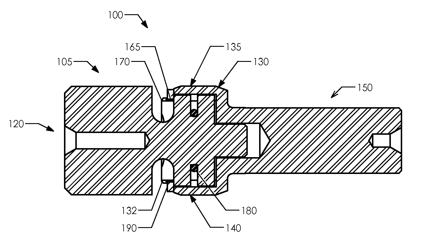
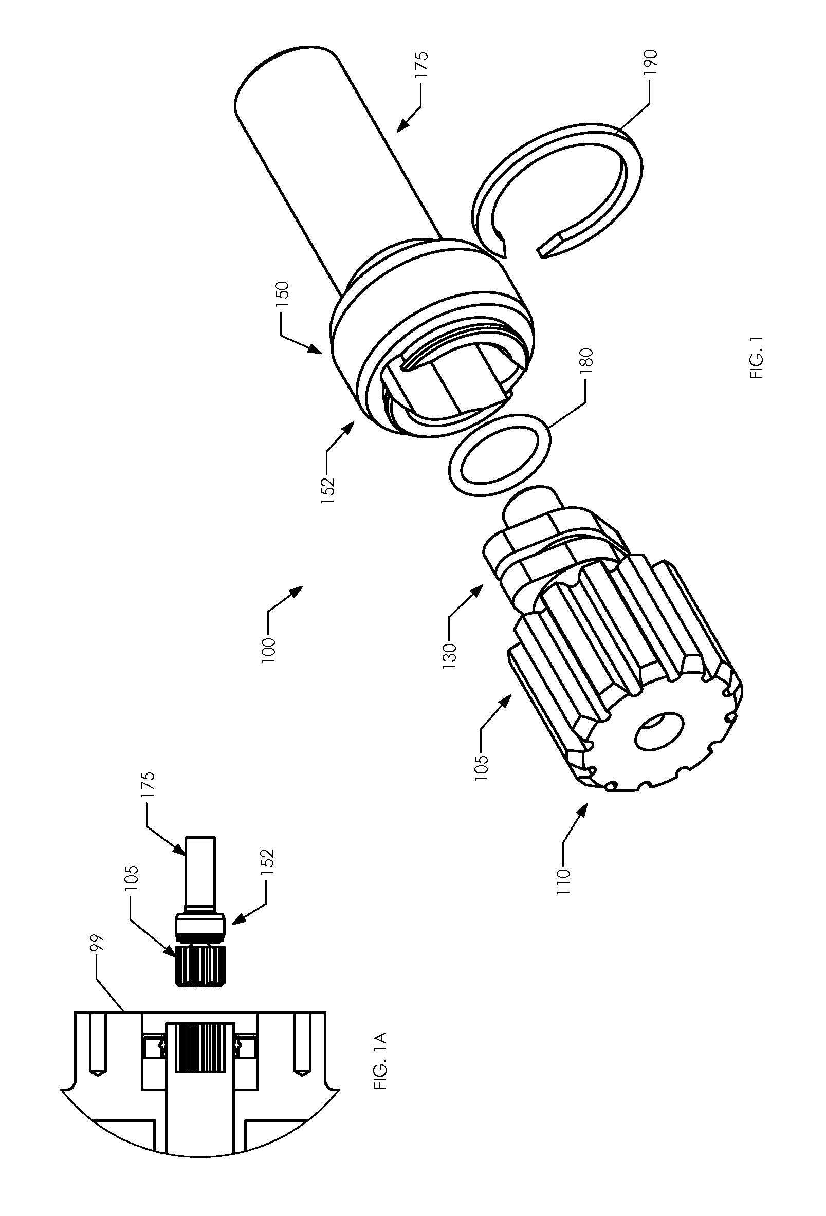
[0025]FIG. 1 is a perspective diagram of a torque-limiting coupling 100 in a disassembled state, comprising a break away spline coupler 105 and a break away spline receiver 150. The break away spline coupler 105 comprises a spline end 110 and a lobe end 130. The break away spline receiver 150 comprises a receiver end 152 and a shaft end 175. In its assembled state, discussed below with reference to FIGS. 4A-4D, the assembled coupler 100 further includes an o-ring 180 and a retaining ring 190.

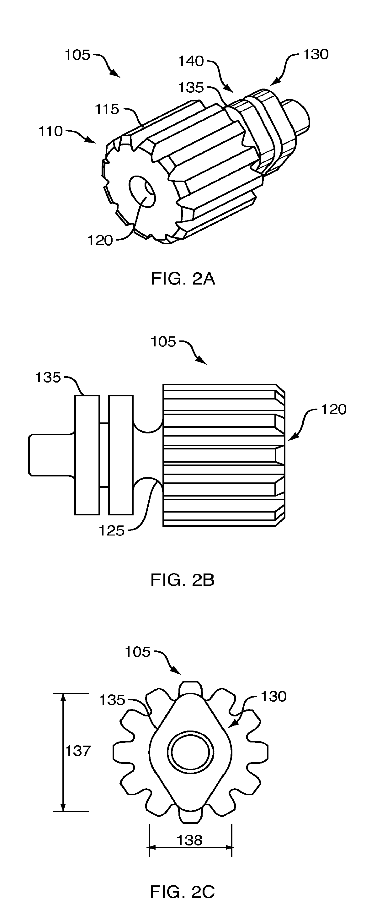
[0026]FIGS. 2A-2F illustrate several views of the break away spline coupler 105 of FIG. 1.

[0027]FIG. 2A is a perspective diagram of the break away spline coupler 105 of FIG. 1. The break away spline coupler 105 comprises a spline end 110 and a lobe end 130. The spline end 110 includes a plurality of longitudinally extending circumferentially spaced splines 115 and is configured to be mated coaxially to a transmission output of a...


PUM

PropertyMeasurementUnit
breaking torqueaaaaaaaaaa
shear stressesaaaaaaaaaa
cross-sectional areaaaaaaaaaaa

Abstract

A torque-limiting coupling may be used to provide a torsion drive between an engine or motor and a driven accessory. If an accessory should experience a catastrophic failure a torsion limit is exceeded and a spline breaks away from the coupling. This guarantees that the internal engine gearing used to drive the accessory is not compromised and interfering with essential moving parts inside the engine. Further, a misalignment compensation limits the side load and wear that occurs when coupling two precision shafts with little clearance on the bearings. With a misalignment coupling, the mount can be slightly out of parallel with no negative effects.

Description

BACKGROUND OF THE INVENTION[0001]It is common for a torsion drive to be employed between an engine and a drive accessory. For example, in automobiles, a belt drive is often used to transfer power from the engine to various accessories, such as a compressor, alternator, generator and numerous pumps. Should any of these accessories experience a catastrophic failure, such as a seized bearing, the accessory will cease functioning and the belt drive will continue to function properly. Although the belt will slip past the non-functioning accessory, possibly causing damage to the belt itself, it is extremely unlikely that damage to other accessories or the engine will occur as a result of the failure of the accessory.[0002]In small aircraft, however, a belt drive is not used to power accessories from an engine. Rather, accessories are driven directly from gears disposed in an accessory case typically located at the rear of the engine. In this design, should a catastrophic failure occur in ...

Claims


Application Information

Patent Timeline
Patent Type & Authority Patents(United States)
IPC IPC(8): F16D9/08
CPCF16D9/08Y10T29/49826
Inventor LISIECKI, JOSEPH, M.
Owner JONES ROBERT M
Why Eureka
Try Eureka