Method and apparatus for feeding a polyurethane mixture into hollow bodies

a polyurethane mixture and hollow body technology, applied in the direction of lighting and heating apparatus, cocoa, sweetmeats, etc., can solve the problems of air bubbles, uneven distribution of mixtures, lack of homogeneity in the structure and density of foam, etc., to reduce the consumption of polyurethane materials, short and homogeneous times, and the effect of accelerating the expansion time of foam

Active Publication Date: 2014-04-29
AFROS
View PDF25 Cites 7 Cited by
  • Summary
  • Abstract
  • Description
  • Claims
  • Application Information

AI Technical Summary

Benefits of technology

[0020]In particular, an object of the invention is to obtain a condition of isometric expansion of the polyurethane foam which, by reacting and expanding at a basically constant speed, is thereby able to reach the farthest edges of the cavity to be filled, in extremely short and homogenous times, i.e. with expansion times which are very similar or basically the same; this reduces the incorporation of air bubbles and limits the collapsing and remixing of the foam which has already expanded and reacted. A foam is obtained which is structurally homogenous and has no excessively flattened cells; the expansion times of the foam can also be accelerated.
[0021]By the method and apparatus according to this invention, thanks to distribution and isometric expansion of the mixture, it is also possible to reduce the consumption of polyurethane material, obtaining a foam having same technical and mechanical characteristics of a polyurethane foam obtained by the traditional technology.BRIEF DESCRIPTION OF THE INVENTION
[0022]The principle on which this invention is based consists in using a conventional high-pressure mixing device, to feed a chemically reactive polyurethane mixture, from an injection point into the cavity of a hollow body, extending in a horizontal plane, starting from a maximum flow-rate value and injection speed to pour the mixture at a first deposition zone positioned at a maximum distance from the injection point, and subsequently continuing the injection by gradually reducing the flow-rates and the injection speeds, allowing the injected mixture to be poured in successive deposition zones, to distribute the mixture from the first deposition zone to a zone closest to the injection point, along a longitudinal distribution strip, while maintaining a constant reaction ratio between the polyurethane components to have a homogeneous distribution and an isometric expansion of the mixture inside the cavity of the hollow body.
[0027]decreasing the flow-rate and the injection speed, making the polyurethane mixture to be poured in one or more successive deposition zones comprised between said farthest deposition zone and a final deposition zone close to the injection point; and

Problems solved by technology

However, injecting the polyurethane mixture against a surface, or in a direction different from the natural running of the mixture, causes several troubles.
In fact, the jet mixture, on hitting a surface or an opposite wall, generates vortexes which, by falling down for gravity, form several sprays and an irregular flowing of the mixture, with consequent inclusion of air bubbles, and lack of homogeneity in the structure and density of the foam.
Although this manner of proceeding allows a sufficient expansion of the polyurethane mixture, it once again causes uneven incorporation of air bubbles and remixing of the subsequently fed with the first injected mixture, which has already started to react and expand; this results in disturbance and partial collapsing of that part of the mixture which is already expanding, all this causing an uneven distribution of the mixture which is higher the greater the space the expanding mixture must cover to reach the farthest points of the cavity.
By increasing the flowing speed of the foam against a surface to reach the farthest parts of the cavity in shorter times, in turn gives rise to the foaming of flattened cells, and a consequent structural unevenness.
A similar solution, while it allows the polyurethane mixture to be distributed along the cavity, involves also a considerably complexity from both constructional and functional viewpoint; this derives from the need to coordinate the backwards movement of the mixing device and the supply pipe, with the speed of the outcoming flow of mixture, and to adopt automation mechanisms necessary to coordinate this movements.
The supply pipe must necessarily be removed after each injection step, or after an extremely limited number of steps, replacing it with a new supply pipe; besides additional costs, this also leads to a consequent slow-down and complication of the productive cycle.

Method used


Image

  • Method and apparatus for feeding a polyurethane mixture into hollow bodies
  • Method and apparatus for feeding a polyurethane mixture into hollow bodies
  • Method and apparatus for feeding a polyurethane mixture into hollow bodies

Examples


Embodiment Construction

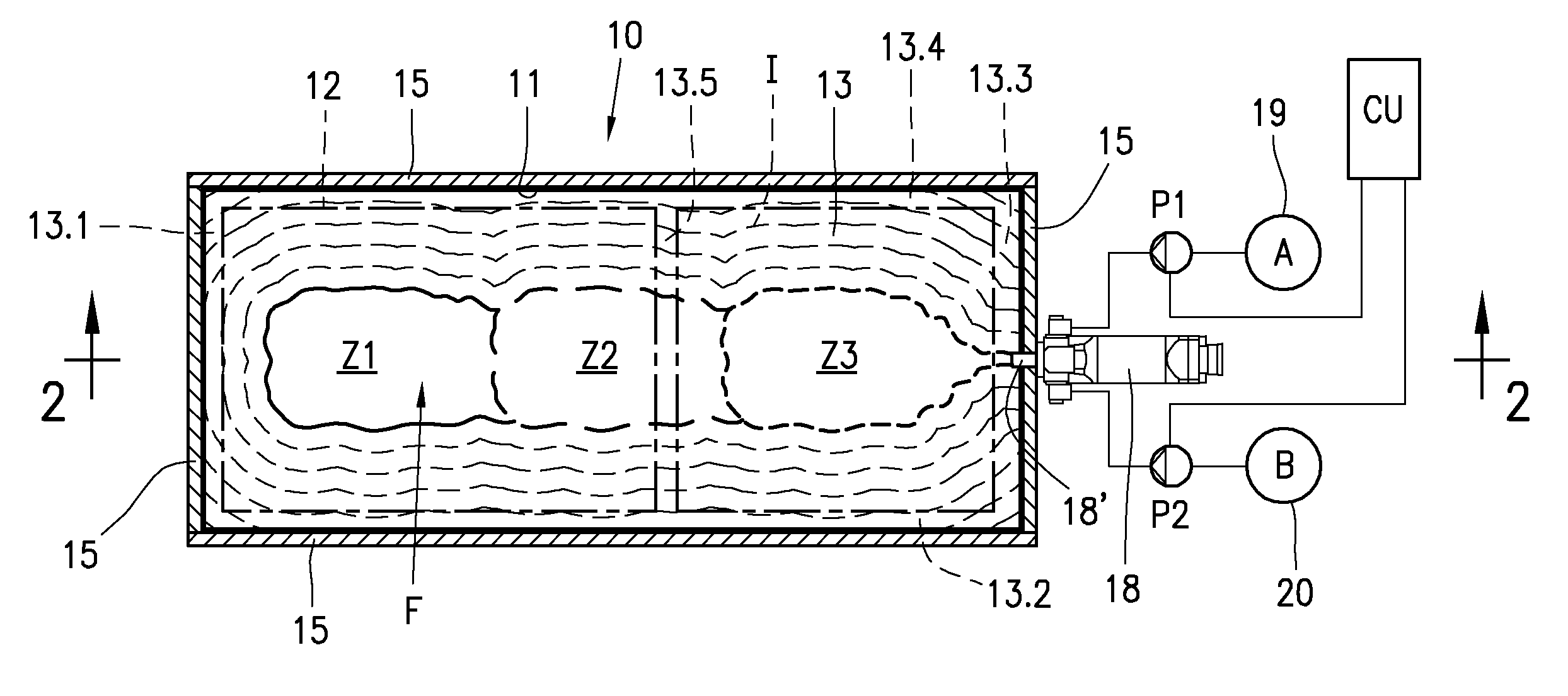
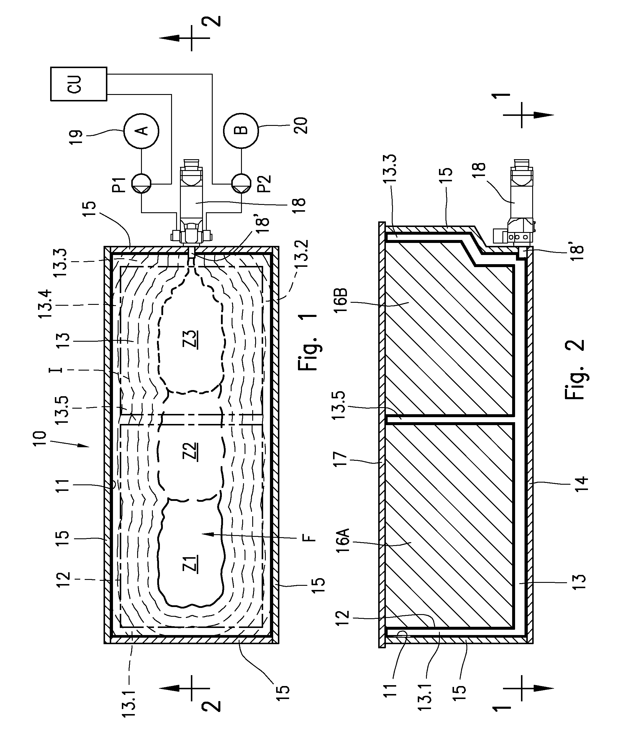
[0051]The method and some embodiments of an apparatus according to the invention will be illustrated in greater detail below, with reference to a polyurethane mixture for the production of a thermally insulating foam into the cavity of hollow walls of a domestic refrigerator cabinet; however, what will be stated with reference to the example of FIGS. 1 and 2 is to be intended for foaming of any other hollow body, for example any type of refrigerator cabinet for household or industrial use, freezers, refrigerated windows, or thermally insulating panels for building or for construction of cold-storage cells, or for any other suitable application.

[0052]FIG. 1 shows a cross sectional view of a refrigerator cabinet 10 for household use, comprising two opposite shells, in particular an external shell 11 and an internal shell 12 which, as shown in FIG. 2, in the assembled condition form a cavity in the hollow wall 13 or back wall of the refrigerator cabinet 10, the hollow side walls 13.1, ...


PUM

PropertyMeasurementUnit
speedaaaaaaaaaa
speedaaaaaaaaaa
speedaaaaaaaaaa

Abstract

A method and apparatus for feeding a polyurethane mixture suitable to form a thermally insulating layer inside hollow bodies, such as hollow walls of a refrigerator cabinet, freezer, display counter or insulating panel. A polyurethane mixture resulting from chemically reactive components, supplied by a high-pressure mixing device, is injected into a cavity of a hollow body extending in a horizontal plain. The mixture is injected at a first flow-rate and a first injection speed, to be poured into a first deposition zone farthest from the injection point. Subsequently, the flow-rate and the injection speed of the polyurethane mixture are gradually reduced in a controlled manner, to be poured in successive deposition zones towards the injection point of the polyurethane mixture, along a distribution strip, allowing the injected mixture to spread out throughout the cavity of the hollow body along isometric expansion lines.

Description

BACKGROUND OF THE INVENTION[0001]This invention refers to a method and an apparatus suitable for feeding a polyurethane mixture to form thermally insulating layers into cavities of hollow bodies extending in a horizontal plane, providing a thermally insulating polyurethane foam for example into the hollow walls of refrigerator cabinets, household or industrial freezers, display counters or insulating panels, normally used in the building field, for cold-storage cells, or for other similar applications.[0002]As known, polyurethane foams have several typical properties: in particular, the reaction between the polyurethane components, such as a polyol and an isocyanate, tends to develop heat and CO2 gas, and cause the release of a foaming agent to generate a foam which rapidly expands, flowing into the cavity of a hollow body to fill it completely.[0003]Polyurethane foams are also the best industrially available thermal insulating materials and are usable for all those applications for...

Claims


Application Information

Patent Timeline
Patent Type & Authority Patents(United States)
IPC IPC(8): B29C44/42B29C44/18B29C44/34
CPCB29C44/60B29B7/7404B29B7/7433B29B7/7615B29B7/7694B29C44/38B29K2075/00B29L2031/7622F25D23/064
Inventor FIORENTINI, CARLOCORTI, MAURIZIO
Owner AFROS
Why Eureka
Try Eureka