Unlock instant, AI-driven research and patent intelligence for your innovation.

Image correction method

a technology of image correction and image, applied in the field of image correction methods, can solve the problems of increasing building the shading table, etc., and achieve the effect of lowering the image correction cost of the scanner device, improving the image effect, and reducing the storage area of the memory storage uni

Active Publication Date: 2014-04-29
FOXLINK IMAGE TECH
View PDF8 Cites 0 Cited by
  • Summary
  • Abstract
  • Description
  • Claims
  • Application Information

AI Technical Summary

Benefits of technology

The patent describes a method for improving the quality of images captured by a scanner device. The method involves storing the values of variables needed for executing a program set by a user in a flash memory, which helps to eliminate spots and dust on the document, resulting in a better image quality. Additionally, by reducing the usage of the flash memory, the method reduces the cost of image correction for the scanner device.

Problems solved by technology

However, in the process of building the above-mentioned shading table to perform the brightness compensation of the image by the image correction method, unpredictable spots or dust on the document will affect the build of the shading table to get an inaccurate shading table and further affect an image correcting effect.
Thus, the scanner device needs to have the memory storage unit 40′ with a larger storage area that increases an image correction cost of the scanner device.

Method used


Image

  • Image correction method
  • Image correction method
  • Image correction method

Examples


Embodiment Construction

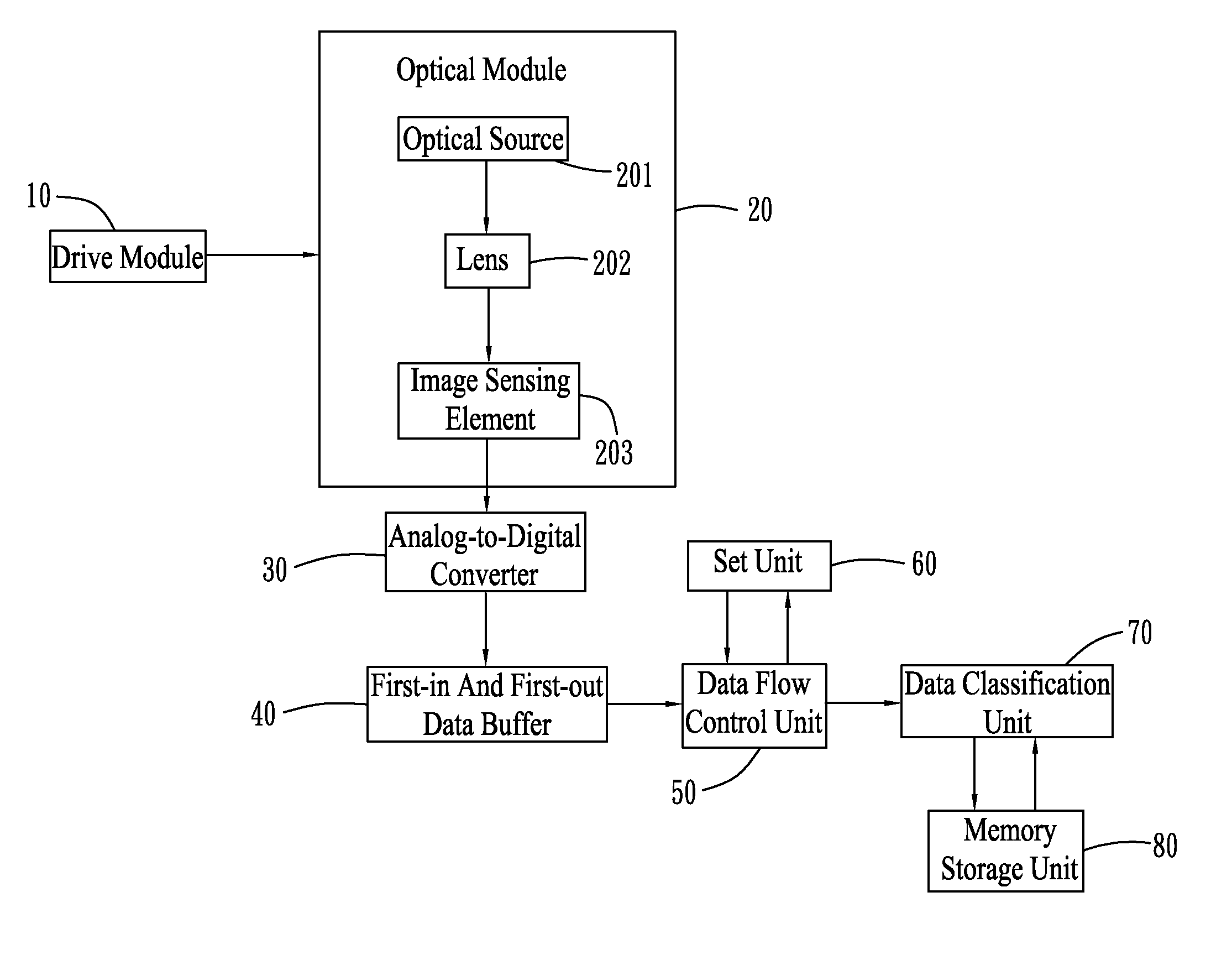
[0014]With reference to FIG. 2, an image correction method in accordance with an embodiment of the present invention is applied to a scanner device (not shown). The scanner device is an automatic feed unit type of single double-sided scanner device, a paper feed type of single double-sided scanner device or a platform single scanner device. In this embodiment, the scanner device is the platform single scanner device, and includes a main case (not shown), a drive module 10, an optical module 20, an analog-to-digital converter 30, a first-in and first-out data buffer 40, a data flow control unit 50, a set unit 60, a data classification unit 70 and a memory storage unit 80. The drive module 10, the optical module 20, the analog-to-digital converter 30, the first-in and first-out data buffer 40, the data flow control unit 50, the set unit 60, the data classification unit 70 and the memory storage unit 80 are electrically connected and are assembled in the main case. The optical module 2...


PUM


Abstract

An image correction method is applied to a scanner device. The scanner device includes a main case, a drive module, an optical module, an analog-to-digital converter, a first-in and first-out data buffer, a data flow control unit, a set unit, a data classification unit and a memory storage unit which are electrically connected and assembled in the main case. The scanner device executes a program statement set by the set unit in the memory storage unit to get values for building an update shading table. The scanner device utilizes the update shading table to compensate pixel values corresponding to red, green and blue light of each scanned line of an image for doing a luminance compensation of image pixels corresponding to the red, green and blue light of each scanned line of the image so as to complete an image correction of each scanned line of the image.

Description

BACKGROUND OF THE INVENTION[0001]1. Field of the Invention[0002]The present invention generally relates to an image correction method, and more particularly to an image correction method which is applied to a scanner device.[0003]2. The Related Art[0004]Referring to FIG. 1, a conventional image correction method is applied to a scanner device. The scanner device generally includes a main case (not shown), a drive module 10′, an optical module 20′, an analog-to-digital converter 30′ and a memory storage unit 40′. The drive module 10′, the optical module 20′, the analog-to-digital converter 30′ and the memory storage unit 40′ are electrically connected and are assembled in the main case. The memory storage unit 40′ is capable of moving in the main case. The optical module 20′ includes an optical source 201′, a lens 202′ and an image sensing element 203′. The image sensing element 203′ is a charge coupled device (CCD) or a contact image sensor (CIS). A top of the main case is disposed ...

Claims


Application Information

Patent Timeline
IPC IPC(8): H04N1/46
CPCH04N1/46H04N1/48H04N1/407
Inventor LIN, CHUN JENLEE, YU HSIANG
Owner FOXLINK IMAGE TECH