Zoom lens

a zoom lens and zoom technology, applied in the field of zoom lenses, can solve the problems of noisy noise generation, movable heavy first lens group, and the inability to achieve the effect of advantageously improving the magnification of images

Inactive Publication Date: 2014-04-29
OM DIGITAL SOLUTIONS CORP
View PDF12 Cites 2 Cited by
  • Summary
  • Abstract
  • Description
  • Claims
  • Application Information

AI Technical Summary

Benefits of technology

[0029]Thus, in the first aspect of the present invention, the first lens group of a zoom lens according to the present invention is anchored at the time of changing the magnification from the wide-angle end toward the telephoto end. Since the first lens group that is likely to be heavy is anchored, the load of the motor for driving the zoom lens can be reduced if the zoom lens is an electromotive zoom lens. Additionally, if no drive mechanism is provided for the first lens group, the zoom lens can be radially downsized. Furthermore, the first lens group is so arranged as to prevent the sound produced by the inner zooming from leaking and provide an advantage for reducing the noise level. Thus, at the time of a zooming operation for taking a moving picture, the zooming operation can be made quiet and smooth, particularly if the zoom lens is an electromotive zoom lens. Finally, this arrangement is advantageous when the zoom lens is to be made dustproof and drip-proof.
[0245]The above-described arrangement provides an advantage for correcting distortions that can easily be produced by the object side lens group and the focus lens group.

Problems solved by technology

Additionally, such a wobbling operation accompanies a problem of noise generation and the generated noise is recorded as sound particularly when the camera is taking a moving picture.
Furthermore, if the image magnification changes remarkably while the focus lens is wobbling, the picked up image appears to be constantly swaying and hence very strange.
While the heavyweight of the first lens group may not give rise to any problem in the case of manual zooming, a movable heavy first lens group is not desirable for electromotive zoom lenses that are employed for most video cameras.

Method used


Image

  • Zoom lens
  • Zoom lens
  • Zoom lens

Examples


example 1-1

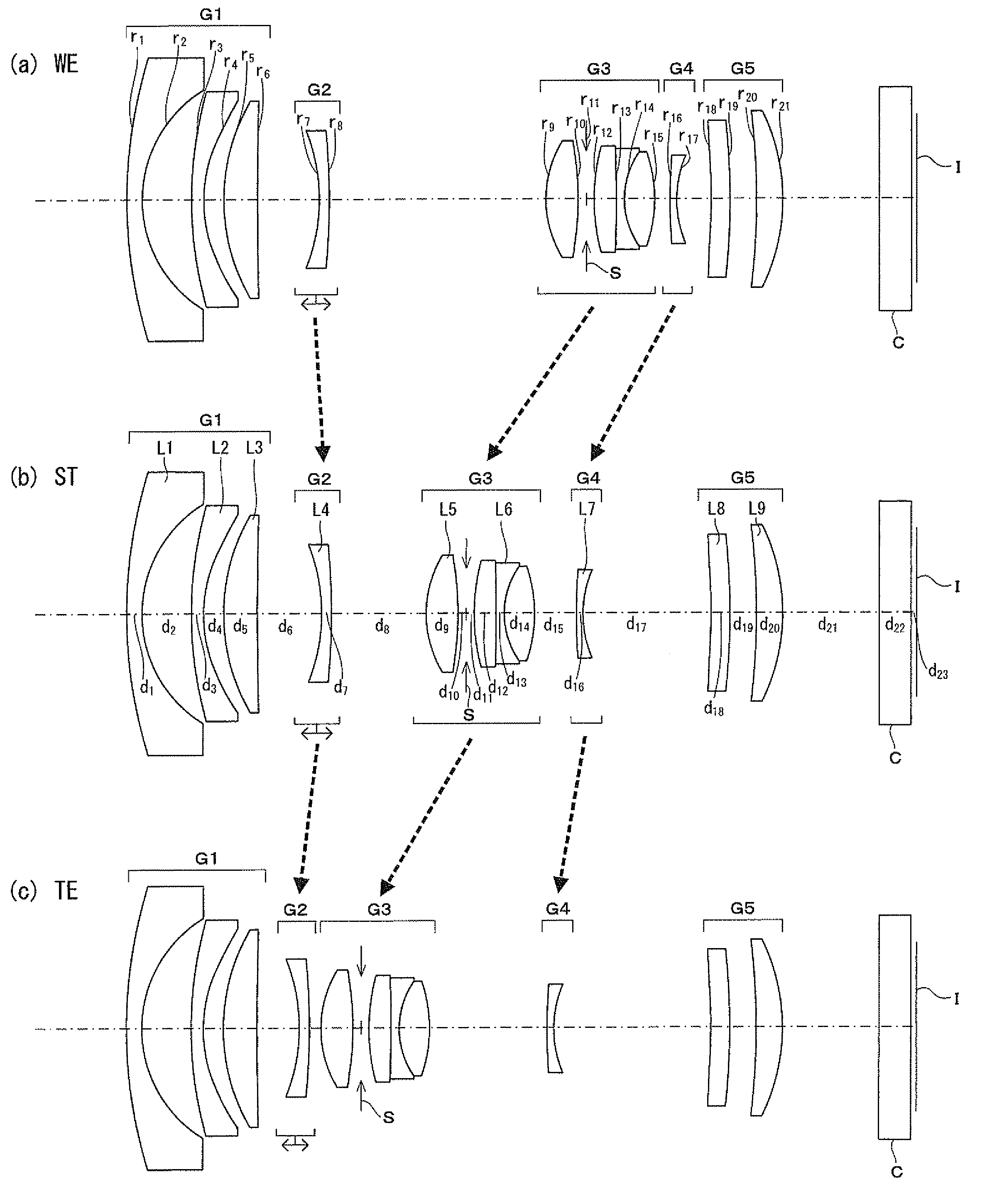
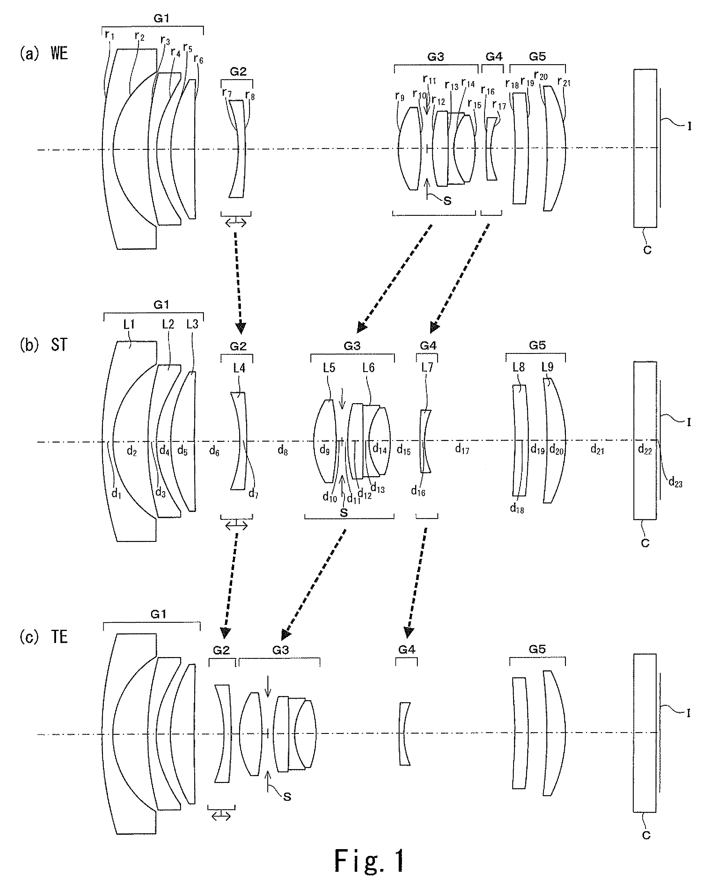
[0300]FIG. 1 is a schematic cross-sectional view of the zoom lens of Example 1-1. As shown in FIG. 1, the zoom lens of Example 1-1 includes a first lens group G1 having a negative power, a second lens group G2 having a negative power, a third lens group G3 having a positive power, a fourth lens group G4 having a negative power and a fifth lens group G5 having a positive power arranged in the above mentioned order from the object side to the image side.

[0301]The first lens group G1 is formed by a negative meniscus lens L1 with its convex surface facing the object side, a negative meniscus lens L2 having two aspheric surfaces with its convex surface facing the object side and a positive meniscus lens L3 with its convex surface facing the object side.

[0302]The second lens group G2 is formed by a negative meniscus lens L4 with its convex surface facing the image side.

[0303]The third lens group G3 is formed by a positive double convex lens L5 having two aspheric surfaces, an aperture S a...

example 1-2

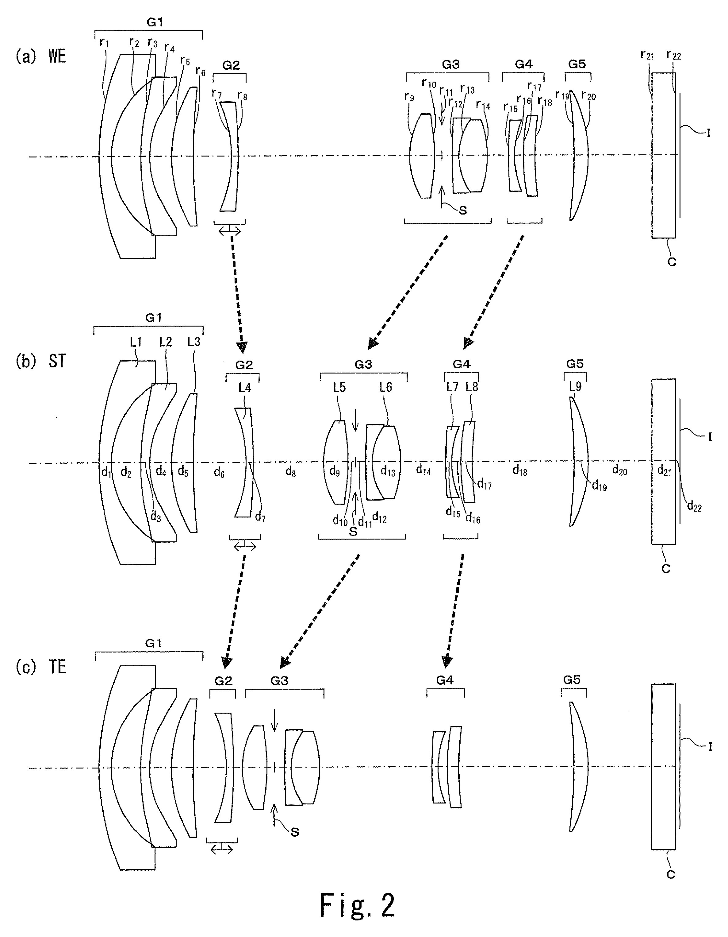
[0308]FIG. 2 is a schematic cross-sectional view of the zoom lens of Example 1-2. The zoom lens of Example 1-2 includes a first lens group G1 having a negative power, a second lens group G2 having a negative power, a third lens group G3 having a positive power, a fourth lens group G4 having a negative power and a fifth lens group G5 having a positive power.

[0309]The first lens group G1 is formed by a negative meniscus lens L1 with its convex surface facing the object side, a negative meniscus lens L2 having two aspheric surfaces with its convex surface facing the object side and a positive meniscus lens L3 with its convex surface facing the object side.

[0310]The second lens group G2 is formed by a negative meniscus lens L4 with its convex surface facing the image side.

[0311]The third lens group G3 is formed by a positive double convex lens L5 having two aspheric surfaces, an aperture S and a cemented lens L6 (lens block) of two lenses including a negative lens and a positive lens.

[0...

example 1-3

[0316]FIG. 3 is a schematic cross-sectional view of the zoom lens of Example 1-3. The zoom lens of Example 1-3 includes a first lens group G1 having a negative power, a second lens group G2 having a negative power, a third lens group G3 having a positive power, a fourth lens group G4 having a negative power and a fifth lens group G5 having a positive power.

[0317]The first lens group G1 is formed by a negative meniscus lens L1 with its convex surface facing the object side, a negative meniscus lens L2 having two aspheric surfaces with its convex surface facing the object side and a positive meniscus lens L3 with its convex surface facing the object side.

[0318]The second lens group G2 is formed by a negative meniscus lens L4 with its convex surface facing the image side.

[0319]The third lens group G3 is formed by a positive double convex lens L5 having two aspheric surfaces, an aperture S and a cemented lens L6 (lens block) of three lenses including a positive lens, a negative lens and...


PUM


Abstract

In a zoom lens of a fixed total length, at the time of changing the magnification from the wide-angle end toward the telephoto end, the first lens group is anchored while the second lens group is moved, and the third and fourth lens groups are moved so as to be located at the object side of the telephoto end relative to the wide-angle end, such that: the interval between the second and third lens groups is decreased at the telephoto end relative to the wide-angle end; the interval between the third and fourth lens groups is increased at the telephoto end relative to the wide-angle end; and the interval between the fourth and fifth lens groups is increased at the telephoto end relative to the wide-angle end, and at the time of focusing a near object point from a remote object point, the second lens group is moved.

Description

[0001]This application claims benefit of Japanese Application No. 2011-33632 filed in Japan on Feb. 18, 2011, and Japanese Application No. 2011-97751 filed in Japan on Apr. 26, 2011 the contents of which are incorporated by this reference.BACKGROUND OF THE INVENTION[0002]The present invention relates to a zoom lens. More particularly, the present invention relates to a zoom lens having a fixed total length that can most suitably be used as interchangeable lens and is advantageous for picking up moving images and also to a zoom lens that can be operated either in the first mode for allowing a wide focusing distance range up to infinity or in the second mode for allowing large imaging magnifications.[0003]There has been a trend of providing digital cameras with a functional capability of picking up moving images in recent years and correspondingly there is a demand for interchangeable lenses that are adaptable to the camera bodies of digital cameras having a function of taking moving ...

Claims


Application Information

Patent Timeline
Patent Type & Authority Patents(United States)
IPC IPC(8): G02B15/14G02B15/173
CPCG02B15/22G02B15/177G02B15/173G02B15/145521G02B15/1461
Inventor KIMATA, HIROHIKOYAMADA, YASUHARUOGATA, YASUJIKAWAMURA, KAZUTERU
Owner OM DIGITAL SOLUTIONS CORP
Why Eureka
Try Eureka