
Multiple mode, bi-directional universal bending apparatus

a multi-mode, universal technology, applied in the direction of forging press details, manufacturing tools, forging presses, etc., can solve the problems of useless common bending tools, and achieve the effects of convenient lock-up in on-site tool boxes, convenient transportation, and low cos

Inactive Publication Date: 2014-05-06
WILSON JR DAVID
View PDF18 Cites 4 Cited by
  • Summary
  • Abstract
  • Description
  • Claims
  • Application Information

AI Technical Summary

Benefits of technology

The machine achieves high torque output with low power input, is compact, lightweight, and adaptable for different materials, allowing efficient bending of heavy wall tubing and other tasks like swaging, while being portable and efficient in energy use.

Problems solved by technology

This makes common bender useless where no power source is available.

Method used


Image

  • Multiple mode, bi-directional universal bending apparatus
  • Multiple mode, bi-directional universal bending apparatus
  • Multiple mode, bi-directional universal bending apparatus

Examples


Embodiment Construction

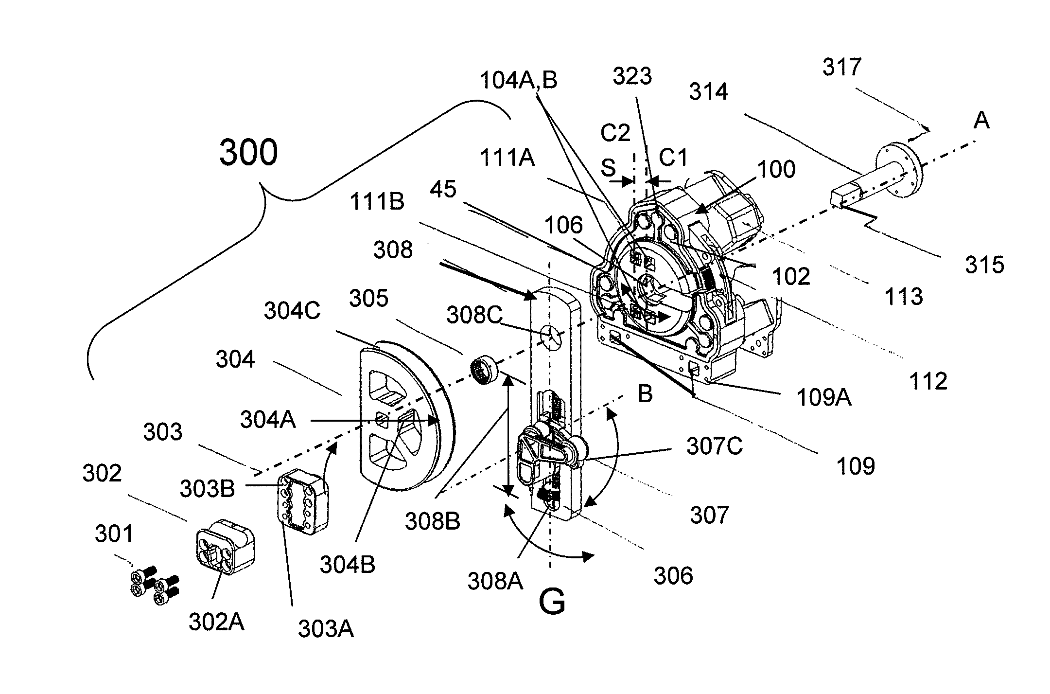
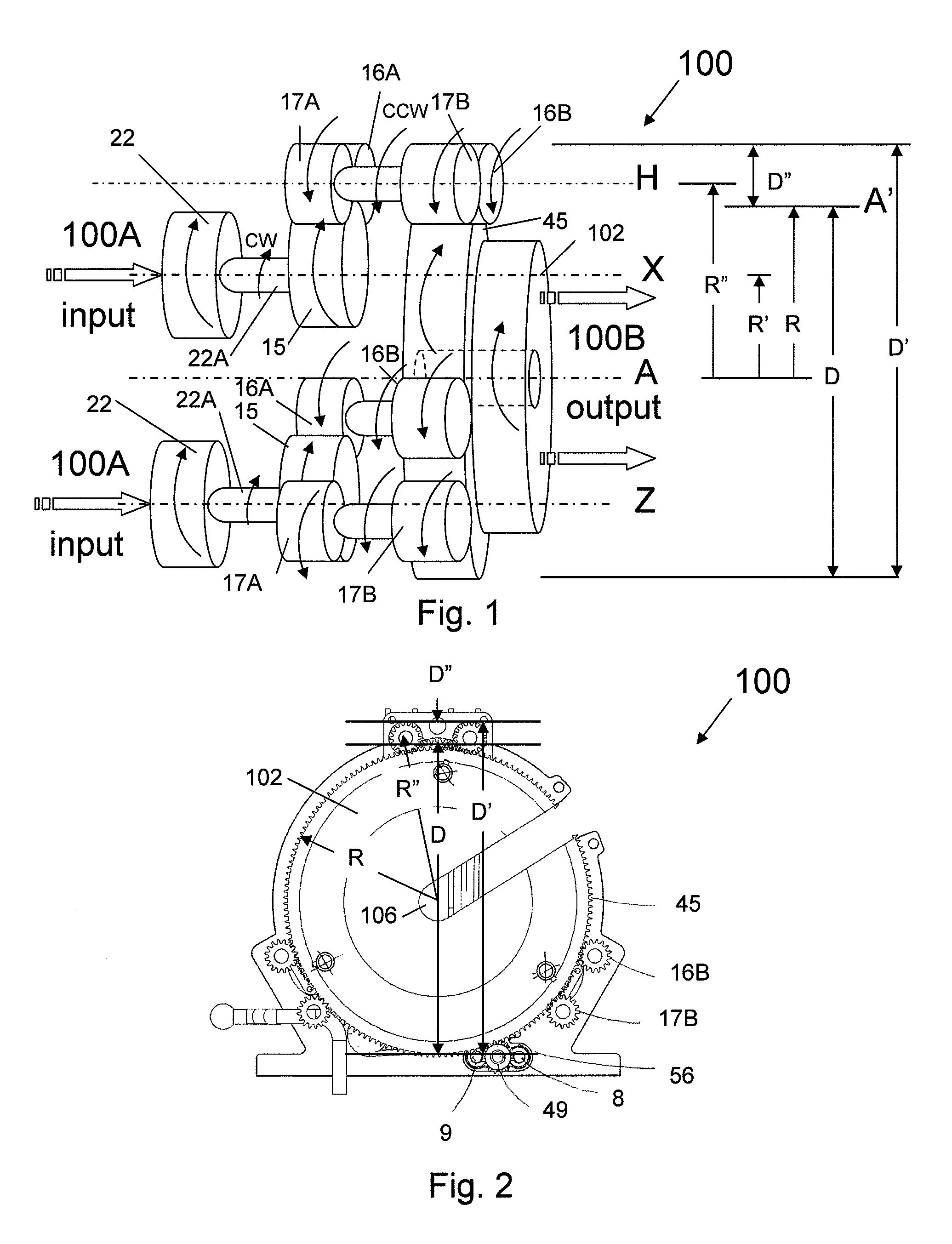
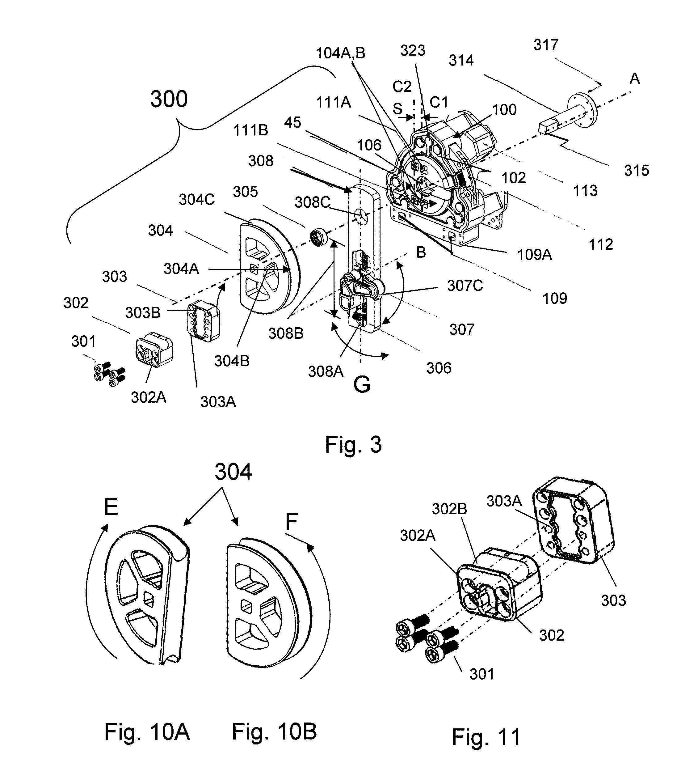
[0039]One aspect of the present invention is illustrated in FIGS. 1 and 2 as a bending apparatus 100 showing relative rotational movements and radial / diametrical orientation of interconnected rotating components driving output drive disk 45 along outer geared circumference 45A having radius R of output drive disk 45. Power input 100A is provided by one or more motors 22 coupled to first (drive) gear 15 that meshes with second (idler) gears 16A, 17A, which are coupled to third (idler) gears 16B, 17B, which mesh with output drive disk 45 to transmit output power 100B through front face 102 to a desired functional attachment tool 300 (FIG. 3), such as a tube bender or swagger, instead of transmitting torque through a shaft disposed along the axis of rotation A of output drive disk 45. Motor 22 will be illustrated herein as an air motor, however, it is contemplated that any other suitable motor (such as an electric motor) is acceptable. Air motor 22 is bi-directional capable of rotating...


PUM

PropertyMeasurementUnit
angleaaaaaaaaaa
voltageaaaaaaaaaa
torqueaaaaaaaaaa

Abstract

Apparatus and methods for use of synchronized plural epicyclical transmissions to stabilize and to drive an output gear of a machine capable of bending tubing, conduit, and pipe requiring high torque, as well as swaging, cutting, and threading. One embodiment of the apparatus includes multiple transmissions encircling and engaged with a centrally mounted motor. Another embodiment of the apparatus includes multiple transmissions, each engaged with a mounted motor. Transmissions can be equidistantly spaced around the perimeter of an output gear.

Description

FIELD OF THE INVENTION[0001]The present invention relates to an apparatus and methods for plural transmissions for rotation of a single output gear, and more particularly, relates to an apparatus and methods for bending tubing, conduit, and pipe requiring high torque.BACKGROUND OF THE INVENTION[0002]Depending on the application, many different bending geometries may be required. For instance electricians often bend conduit at a 90 degree angle to turn a corner while installing wiring in a commercial building, or make large sweeping nested bends to stack a successive series of bends with decreasing radius to enclose and shield electrical wiring.[0003]Principally there are three primary methods of bending a piece of tubing with conventional bending equipment: rotary compression where a set of follower wheels pressures the tubing around a mandrel; rotary draw where the end of the tubing is captured by a lug on the bending mandrel, pulled around the circumference of the mandrel, and inc...

Claims


Application Information

Patent Timeline
Patent Type & Authority Patents(United States)
IPC IPC(8): B21J9/18
CPCB21D7/024B21D7/022
Inventor WILSON, JR., DAVID
Owner WILSON JR DAVID
Learn More