

Receptacle cage, receptacle assembly, and transceiver module assembly
a technology of transceiver module and assembly, which is applied in the direction of aperture leaage reduction, coupling device connection, instruments, etc., can solve the problems of noise radiation, difficult to tightly seal the gap between the outer peripheral portion of the optical module and the inside of the transceiver module, and harmful to other electronic components on the circuit board. achieve the effect of reliable suppression of noise radiation
- Summary
- Abstract
- Description
- Claims
- Application Information
AI Technical Summary
Benefits of technology
Problems solved by technology
Method used
Image

Examples
Embodiment Construction
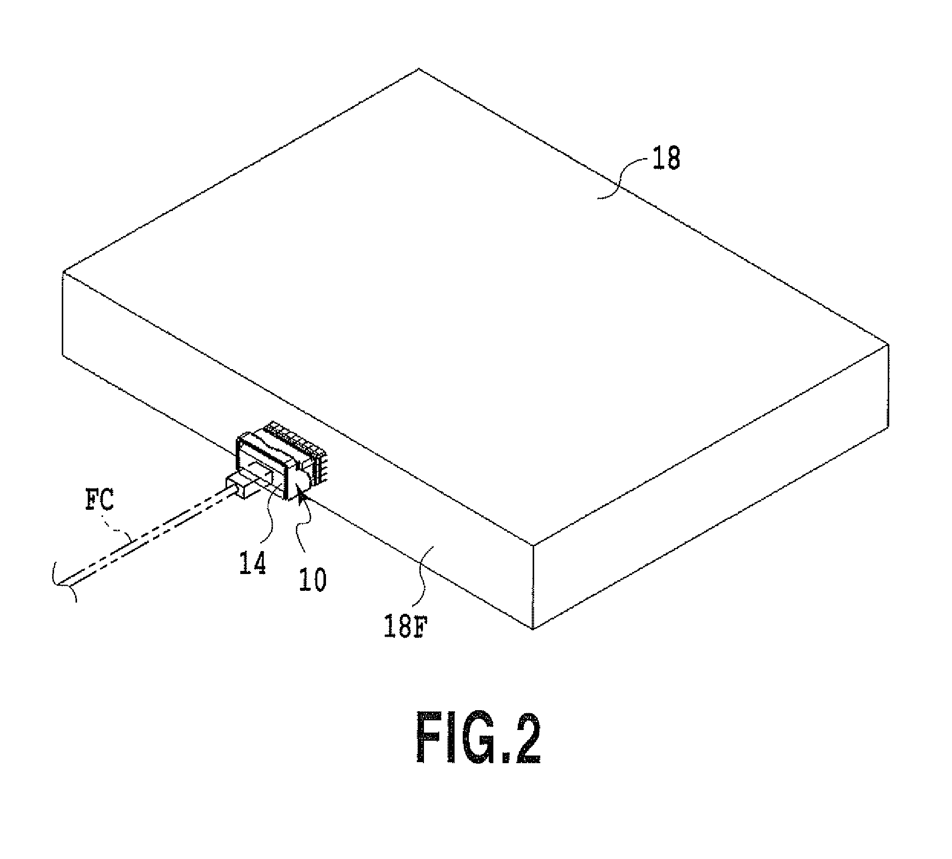
[0040]FIG. 2 shows an example of a transceiver module assembly according to the present invention together with a housing 18 for embedding the assembly.
[0041]An end portion of an optical module 14 of a transceiver module assembly 10 to be described later protrudes out of an operating side end surface 18F of the housing 18. An optical connector, to which one end of an optical cable FC is connected, is connected to a port provided at the end portion of the optical module 14. Another end of the optical cable FC is connected to an optical connector of another housing which constitutes an unillustrated communication system.
[0042]As shown in FIG. 3, the housing18 configured to define an enclosed space inside contains a printed wiring board 16 on which the transceiver module assembly 10 is mounted. In FIG. 3, one transceiver module assembly 10 is mounted on one printed wiring board 16. However, the present invention is not limited only to this configuration and multiple transceiver module ...
PUM
 Abstract
Description
Claims
Application Information