Eddy current probe for surface and sub-surface inspection

Inactive Publication Date: 2014-05-06
NASA
View PDF30 Cites 3 Cited by
  • Summary
  • Abstract
  • Description
  • Claims
  • Application Information

AI Technical Summary

Benefits of technology

[0007]In accordance with the present invention, an eddy current probe for surface and sub-surface inspection includes an excitation coil having windings that are coupled to a low-frequency alternating current (AC) source. A magnetoresistive sensor is centrally disposed within the excitation coil and at one end of the excitation coil to thereby define a sensing end of the eddy current probe. In use, the sensing end of the eddy current probe is positioned adjacent to a surface of a structure. The magnetoresistive sensor has an axis of sensitivity. A tubular flux-focusing lens is disposed between the excitation coil and the magnetoresistive sensor to prevent magnetic cou

Problems solved by technology

However, these conventional eddy current probes are not particularly effective at

Method used


Image

  • Eddy current probe for surface and sub-surface inspection
  • Eddy current probe for surface and sub-surface inspection
  • Eddy current probe for surface and sub-surface inspection

Examples


Example

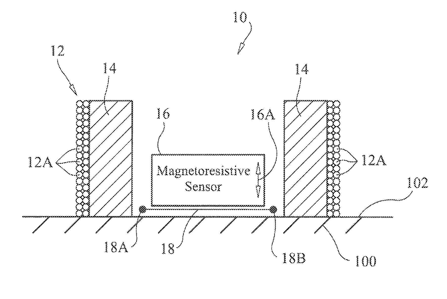
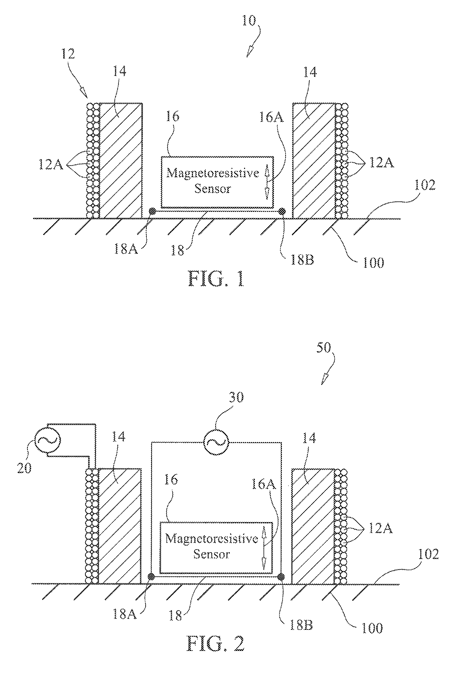
[0015]Referring now to the drawings and more particularly to FIG. 1, an eddy current probe in accordance with an embodiment of the present invention is shown and is referenced generally by numeral 10. As will be explained further herein, eddy current probe 10 is capable of detecting anomalies under a surface 102 of a structure 100 as well as on surface 102. Structure 100 could be, but is not limited to, a laminated structure such as those used in fabricating aircraft structures.

[0016]Probe 10 illustrates only those elements that form the measurement “head” of an eddy current probe system that will be described later herein. Further, probe 10 only illustrates the elements involved with making measurements as probe 10 will generally include various mechanical features (not shown) to support the measurement elements as would be understood by one of ordinary skill in the art.

[0017]For deep flaw detection, probe 10 can include features of the magneto resistive flux-focusing eddy current ...


PUM


Abstract

An eddy current probe includes an excitation coil for coupling to a low-frequency alternating current (AC) source. A magnetoresistive sensor is centrally disposed within and at one end of the excitation coil to thereby define a sensing end of the probe. A tubular flux-focusing lens is disposed between the excitation coil and the magnetoresistive sensor. An excitation wire is spaced apart from the magnetoresistive sensor in a plane that is perpendicular to the sensor's axis of sensitivity and such that, when the sensing end of the eddy current probe is positioned adjacent to the surface of a structure, the excitation wire is disposed between the magnetoresistive sensor and the surface of the structure. The excitation wire is coupled to a high-frequency AC source. The excitation coil and flux-focusing lens can be omitted when only surface inspection is required.

Description

CROSS-REFERENCE TO RELATED PATENT APPLICATIONS[0001]This patent application claims the benefit of and priority to U.S. Provisional Patent Application No. 61 / 479,918, filed on Apr. 28, 2011, the contents of which are hereby incorporated by reference in their entirety.STATEMENT REGARDING FEDERALLY SPONSORED RESEARCH OR DEVELOPMENT[0002]The invention was made in part by an employee of the United States Government and may be manufactured and used by or for the Government of the United States of America for governmental purposes without the payment of any royalties thereon or therefor.FIELD OF THE INVENTION[0003]This invention relates to eddy current probes. More specifically, the invention is an eddy current probe for inspecting a structure's surface and sub-surface regions.BACKGROUND OF THE INVENTION[0004]Non-destructive evaluation (NDE) technologies are used to inspect a variety of structures for fatigue and corrosion damage. One type of NDE technology is an eddy current probe that in...

Claims


Application Information

Patent Timeline
IPC IPC(8): G01N27/82G01B7/16G01R33/14G01N27/72G01R33/00
CPCG01R33/091G01R33/12
Inventor WINCHESKI, RUSSELL A.SIMPSON, JOHN W.
Owner NASA
Why Eureka
Try Eureka