
Signaling protocol for multi-domain optical networks

a multi-domain optical network and signaling protocol technology, applied in the field of optical network signals, to achieve the effect of minimizing the amount of wavelength conversion, minimizing the total resources consumed for the connection, and fast recovery tim

Active Publication Date: 2014-05-06
PERSPECTA LABS INC
View PDF14 Cites 2 Cited by
  • Summary
  • Abstract
  • Description
  • Claims
  • Application Information

AI Technical Summary

Benefits of technology

[0019]A multi-domain optical network provisioning methodology that keeps resource information private in each domain, but optimizes connection setup equivalent to full information sharing across domains is disclosed. The present invention considers both shared mesh restoration and dedicated 1+1 protection. Shared mesh restoration is much more efficient than dedicated 1+1 protection, but 1+1 protection has a faster recovery time than shared mesh restoration. The present invention provides the capability to minimize the amount of wavelength conversion required. In optical networks providing shared mesh restoration or 1+1 protection, it is desirable to consider many possible paths for the working and restoration / protection paths, and optimize the choice of what paths to use for working and restoration / protection so as to minimize the total resources consumed for the connection. For working path choices it is desirable to minimize the path length and the amount of wavelength conversion required. For the shared restoration path it is desirable to use as much shared capacity as possible, so the amount of additional wavelength capacity reserved for restoration is minimized. For the 1+1 working and protection path choices it is desirable to minimize the combined working and protection path length and the combined working and protection path use of wavelength conversion. The present invention collects information that allows these resource usage considerations to be made. In addition, the present invention collects information in each domain and passes on summary information for each domain so that an optimal choice of end-to-end working and restoration / protection paths can be made that is equivalent to what can be achieved with a centralized entity (e.g., a PCE) having a global view of the multi-domain network state. This is highly significant, because the constraint that detailed topology and network state information cannot be shared across domains precludes such a centralized capability. Thus, the present solution achieves a centralized global optimality without violating the sharing of information across domains.

Problems solved by technology

This is highly significant, because the constraint that detailed topology and network state information cannot be shared across domains precludes such a centralized capability.

Method used


Image

  • Signaling protocol for multi-domain optical networks
  • Signaling protocol for multi-domain optical networks

Examples


Embodiment Construction

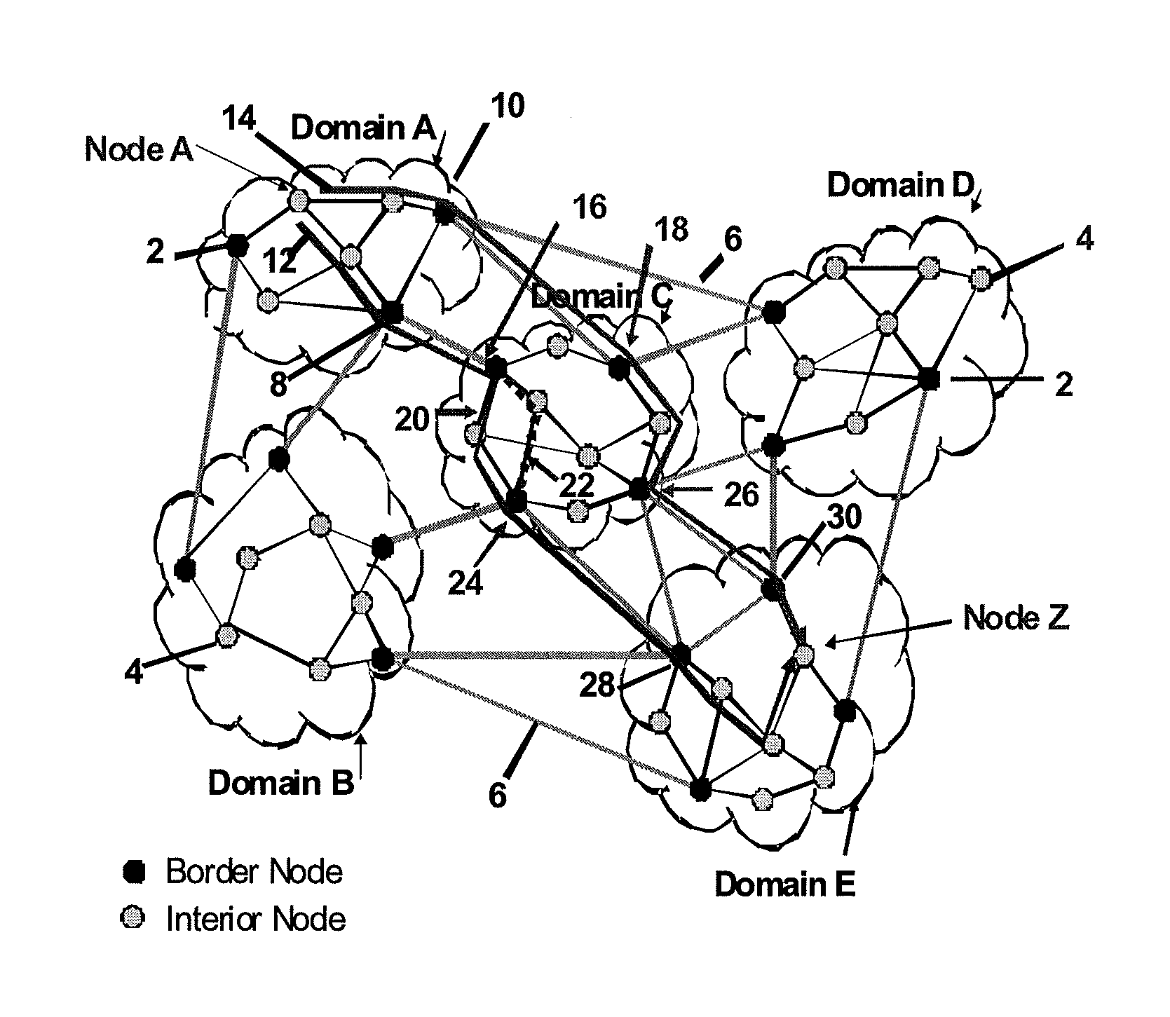
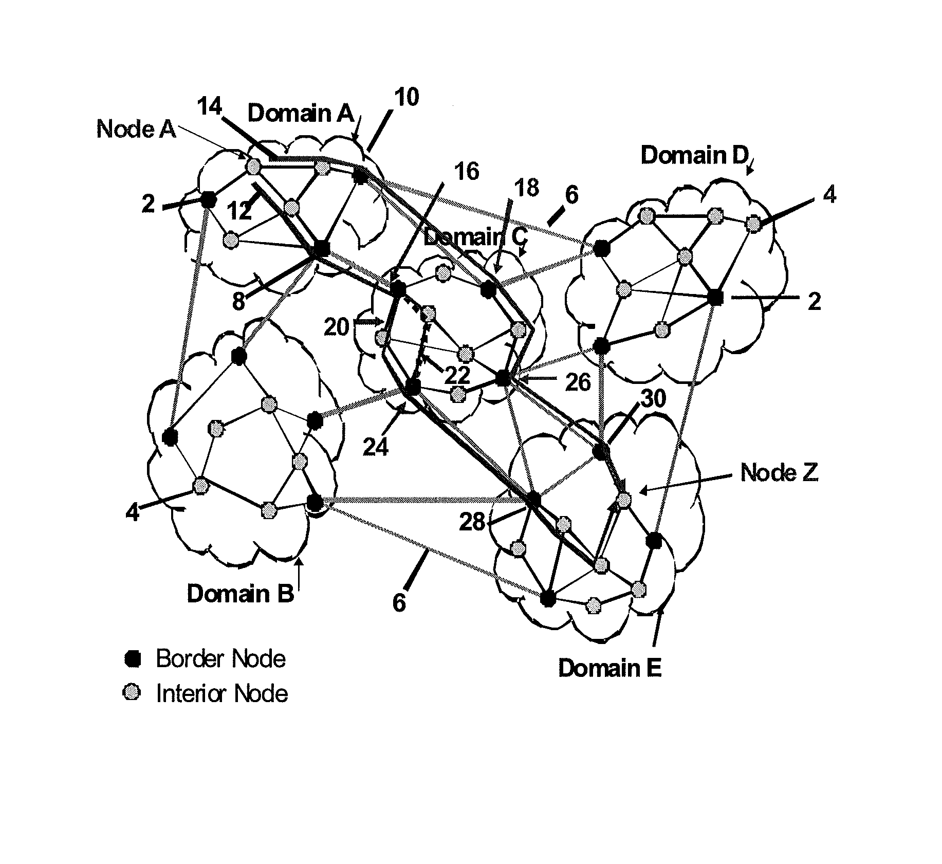
[0027]The FIGURE shows an illustration of a multi-domain network. There are five domains (A, B, C, D, and E) each illustrated as a network within a cloud. Domain border nodes 2 are represented as black circles, and domain interior nodes (non-border nodes) 4 are represented as shaded circles. Border nodes are used to connect from one domain to another. Connections between border nodes in different domains are represented by links 6. As indicated above, these links are known as E-NNI links, and OEO processing is done on each end of the E-NNI link. Therefore there is no need to consider maintaining wavelength continuity between these links and links they connect to within a domain. The present invention is concerned with how to quickly set up wavelength connections between two nodes in different domains. A wavelength connection can consist of one or more wavelength channels. For purposes of simplicity only, the specification will restrict description to setting up a single wavelength c...


PUM


Abstract

A three-way handshake method for optical messaging in a multi-domain optical network that includes a first pass from a source domain to a destination domain through intermediate domains on candidate working paths, collecting information identifying available routing resources for each working path, calculating a working path metric and storing each of the metrics at the respective border node, determining a path key of the topology of each domain working path and using the path key to identify the path outside its domain and determining the best working paths and border nodes to use. A second pass using the path keys for identifying the working path in each domain and reserving the identified routing resources and selecting which routing resources to use. A third pass identifying the selected routing resources and establishing an optical signaling message path between the source node and the destination node.

Description

CROSS REFERENCE TO RELATED APPLICATION[0001]This application is related to U.S. Patent Application Publication No. US 2010 / 0074623 A1, the disclosure of which is hereby incorporated by reference.FIELD OF THE INVENTION[0002]The present invention relates to optical network signals and more particularly to signaling protocols for multi-domain optical networks.BACKGROUND OF THE INVENTION[0003]There are numerous difficulties in setting up optical connections in a multi-domain Wavelength Division Multiplex (WDM) optical network. Multi-Domain means that there are interconnected optical network domains. Each optical network domain is operated by a different administrative entity; typically each administrative entity is a telecommunications carrier. A multi-domain optical network requires setting up point-to-point optical connections that have their end-points in different domains. One important goal is to be able to set up end-end multi-domain connections very quickly (e.g., ranging from 10...

Claims


Application Information

Patent Timeline
Patent Type & Authority Patents(United States)
IPC IPC(8): H04L12/28
CPCH04J14/0284H04J14/0267H04J14/0294H04J14/0227H04J14/0212H04J14/0256H04J14/0268H04L47/724
Inventor SKOOG, RONALD, A
Owner PERSPECTA LABS INC
Learn More