Testing performance of a wireless device

a wireless device and performance testing technology, applied in the direction of pulse manipulation, transmission monitoring, pulse technique, etc., can solve the problems of failure to perform, difficulty in predicting the performance of wireless devices, and high cost of developing, purchasing, selling and deploying new wireless technologies or products, so as to achieve less cost, less time-consuming, and greater capability

Inactive Publication Date: 2014-05-06
AZIMUTH SYSTEMS
View PDF4 Cites 14 Cited by
  • Summary
  • Abstract
  • Description
  • Claims
  • Application Information

AI Technical Summary

Benefits of technology

[0010]The use of a reverberation chamber together with a channel emulator for OTA tests provides an advantage over prior art technology because the resulting test system is less costly that an anechoic chamber test system and has greater capability than a mechanical system based on a reverberation chamber alone. Additionally, evaluation of device performance may be achieved with a less time consuming process allowing more efficient test of the devices. Operation of the reverberation chamber with the channel emulator is enabled by using the channel emulator to drive multiple antennas within the reverberation chamber, wherein the number of antennas being driven is greater than the spatial rank of the signal structure. Furthermore, the antennas are driven individually by a plurality of independent fading processes in order to create a more Gaussian process at the DUT and reduce limitations of capacity due to keyhole effects or non-Rayleigh fading statistics.
[0012]Another advantage is that the drive antennas may be selectively oriented in the test chamber to create channel conditions, such as Rayleigh or Ricean fading. For example, the antennas may be deployed such that no line-of-sight transmission component exists from the test system antennas to the DUT antennas. In one embodiment this is accomplished by positioning the test system antennas such that signals are directed away from the DUT, e.g., into the corners of the test chamber. In another embodiment the antennas are positioned such that a line-of-sight transmission component exists from the test system antennas to the DUT antennas.
[0013]Another advantage is that the reverberation chamber in this solution can be smaller than a reverberation chamber without the use of a channel emulator solution as the channel emulator electronics driving a large number of antennas can be used to create the statistical Rayleigh fading. Without the use of these components, the chamber must be physically larger to create a statistically Rayleigh environment.

Problems solved by technology

Testing is performed to mitigate the risk that devices will fail to perform as planned because the costs associated with developing, purchasing, selling and deploying a new wireless technology or products are often quite high.
However, wireless device performance is notoriously difficult to predict because it can be affected by many factors.
The different conditions to which a wireless device may be subjected in actual use is so great in number that it is difficult and time-consuming to create all of those conditions in a test environment.
However, this technique is too labor intensive and imprecise to simulate a wide variety of traffic conditions, distances between devices and rates of motion in a practical manner.
Further, such a manual, open-air test can be rendered invalid by transient interference from a microwave, RADAR or other RF source.
However, anechoic chambers are relatively large and costly.
The techniques required to produce the channel conditions may also require a large number of channel emulator electronics and antennas.
Additionally, calibration of such a system and performing isotropic measurements in such a system are typically very time consuming.
However, mechanical systems are not well suited to providing Doppler conditions similar to those experienced by an actual DUT in fast motion, such as in an automobile or train, due to the speed limits of the stirrers.
Consequently, reverberation chambers are generally limited to reproducing conditions of low Doppler frequencies and simple decaying exponential power delay profiles or for testing that does not require realistic channel conditions.
However, conducted testing also has some drawbacks.
Furthermore, as will be explained in greater detail below, bypassing the antenna may compromise the value of the test results as the device is not tested in the same form it will be sold or used.
Recent advances in wireless technology present even more difficult challenges to designers of test systems.

Method used


Image

  • Testing performance of a wireless device
  • Testing performance of a wireless device
  • Testing performance of a wireless device

Examples


Embodiment Construction

[0020]Some aspects of the invention may be implemented by one or more computer programs. Such computer programs are stored in non-transitory computer-readable memory and executed by processing hardware in apparatus described below to perform functional steps such as those described below.

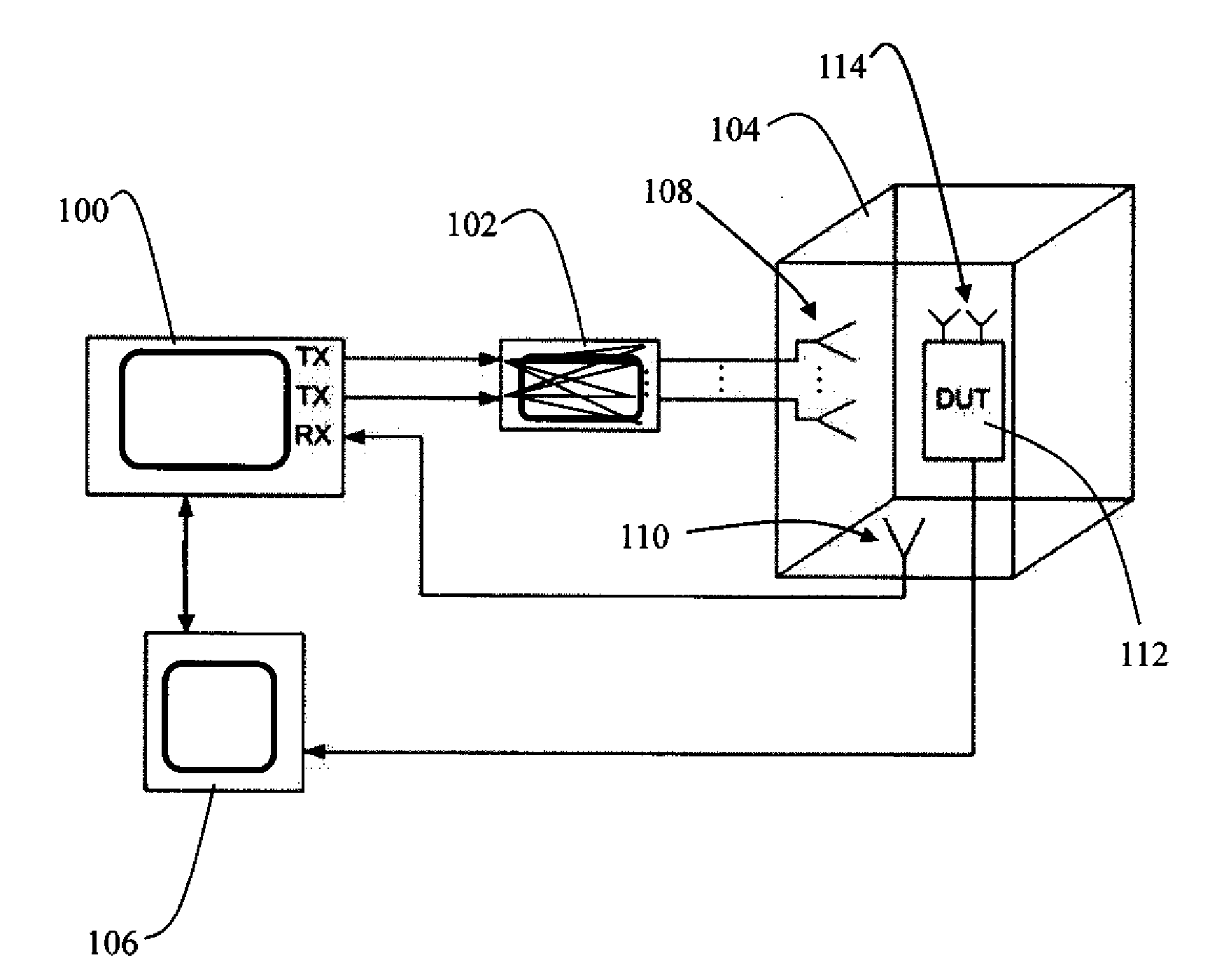
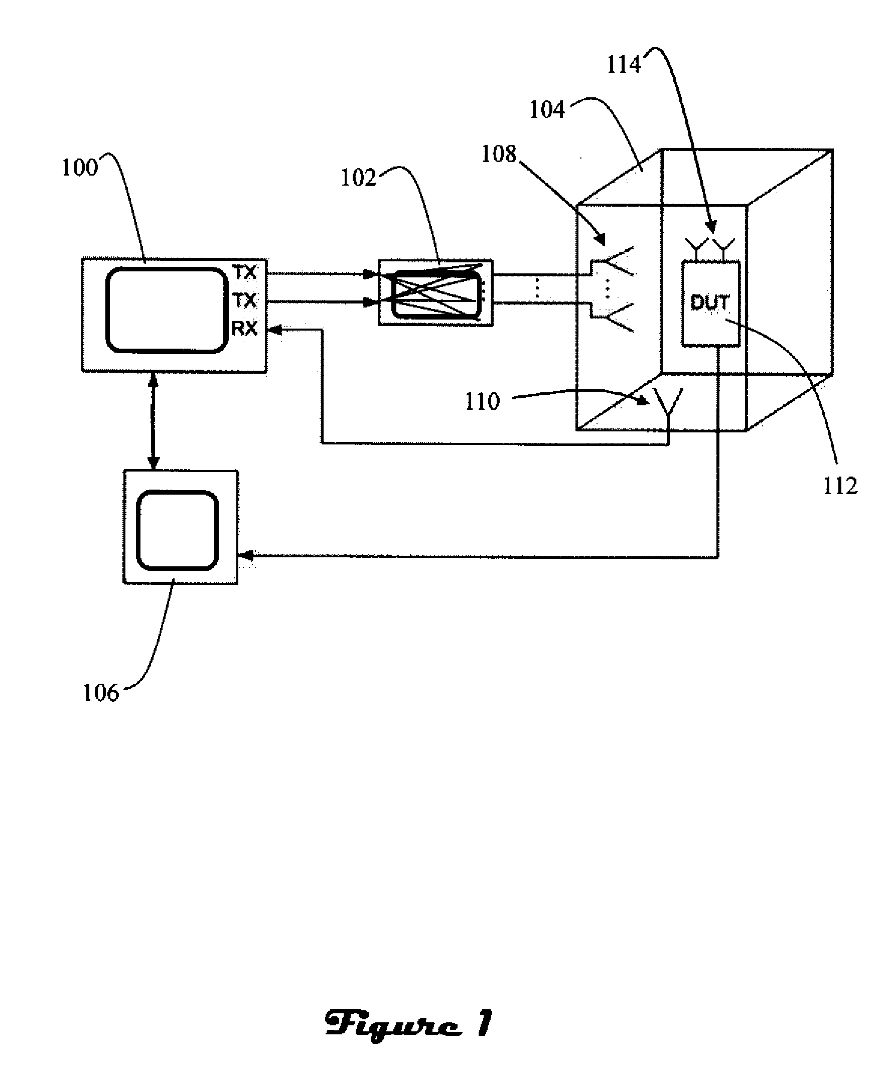
[0021]FIG. 1 illustrates an OTA test system in accordance with an embodiment of the present invention. The system includes a signal transmission emulator 100, a channel emulator 102, a test chamber 104, and a performance metric measurement module 106. The signal transmission emulator 100 transmits signals to the channel emulator 102. The channel emulator 102 operates on the signals from the signal transmission emulator 100 and transmits a corresponding output signal into the test chamber 104 via antennas 108. A sniffer antenna 110 associated with the test chamber provides a return signal from a DUT 112 to the signal transmission emulator 100, when necessary. Parameters captured from or by the DUT 11...


PUM


Abstract

Improved performance testing of a wireless device is disclosed. The system is particularly suited to testing devices having multiple antennas. The device under test (DUT) is placed in a reverberation chamber with antennas for transmission of a test signal to the DUT. The number of antennas deployed in the reverberation chamber and placement of those antennas is selected such that no line-of-sight transmission component exists from test system antenna to DUT antenna, and the number of antennas deployed in the reverberation chamber is greater than the spatial rank of the signal. The antennas are driven by a programmable channel emulator capable of generating fading, correlation, delay, Doppler and other channel condition phenomena. Furthermore, the antennas are driven individually by a plurality of independent fading processes. The combination of the programmable channel emulator and reverberation chamber creates a multipath environment which simulates signals arriving from different locations, with different delays, as well as the simulation of device motion. The system also includes instruments to produce test signals and to measure the performance of the DUT.

Description

CROSS-REFERENCE TO RELATED APPLICATIONS[0001]This application claims priority to U.S. Provisional Patent Application 61 / 305,760, titled TESTING PERFORMANCE OF A WIRELESS DEVICE, filed Feb. 18, 2010.BACKGROUND OF THE INVENTION[0002]The present invention is related to testing performance of wireless devices. Mobile phones, PDAs, tablet computers, and laptop computers and other wireless devices are widely used. Such devices typically communicate with a wireline computer network via an base station or cell tower, thereby allowing mobility. Various improvements in wireless technology have enabled wireless devices to be built in a smaller form factor with increased throughput and computing power. Testing is performed to mitigate the risk that devices will fail to perform as planned because the costs associated with developing, purchasing, selling and deploying a new wireless technology or products are often quite high. However, wireless device performance is notoriously difficult to predi...

Claims


Application Information

Patent Timeline
Patent Type & Authority Patents(United States)
IPC IPC(8): H04Q1/20H04B17/00H04B3/46
CPCH04W24/00H01Q3/267
Inventor GRIESING, JOHN ROBERTWRIGHT, CHARLES R.
Owner AZIMUTH SYSTEMS
Why Eureka
Try Eureka