Apparatus and method for reinforcing jet pump riser

a technology of riser and riser, which is applied in the direction of plant pumping arrangement, siphon, bend, etc., can solve the problems of cracks, cracks that may rupture the welded portion, and are difficult to maintain a function, so as to prevent the crack from occurring and prevent the crack from developing

Active Publication Date: 2014-05-06
KK TOSHIBA
View PDF12 Cites 8 Cited by
  • Summary
  • Abstract
  • Description
  • Claims
  • Application Information

AI Technical Summary

Benefits of technology

[0018]The present invention was conceived in consideration of the circumstances mentioned above, and an object of the present invention is to provide an apparatus and a method for reinforcing a jet pump riser for preventing occurrence of a crack, for preventing development of the crack that has occurred, and for maintaining a function of the jet pump riser even in the unlikely event that the crack develops and a jet pump is damaged by mounting the apparatus to the jet pump riser in which the crack is found in a welded portion.
[0032]According to the present invention described above, by mounting the reinforcing apparatus to the jet pump riser in which it is determined that the crack may occur in a welded portion or the crack is found in the welded portion, it is possible to prevent the crack from occurring or to prevent development of the crack that has occurred. In addition, even in the unlikely event that the crack develops and the jet pump is damaged, it is possible to maintain a function of the jet pump riser

Problems solved by technology

Further, during the operation, stress due to a pressure difference between the inside and outside and a large quantity of heat at a reactor core portion occur, and a thermal stress acts on the jet pump.
Further, cracks may be produced by the stress corrosion crack that occurs in a sensitized region of a welding heat-affected zone.
By continuing the operation of the reactor, the crack may develop to rupture the welded portion in extreme cases.
As a result, it may be difficult to maintain a function of sending the fluid (water) into the reactor core of the jet pump, which provides an inconvenience from a viewpoint of safely maintaining operation of the reactor.
These methods may complicate behavior of oscillation applied to the jet pump 1a and also exert undesirable influence on the welded portion between the diffuser 13 and the shroud support plate 5.

Method used


Image

  • Apparatus and method for reinforcing jet pump riser
  • Apparatus and method for reinforcing jet pump riser
  • Apparatus and method for reinforcing jet pump riser

Examples


first embodiment (

FIGS. 1 to 4)

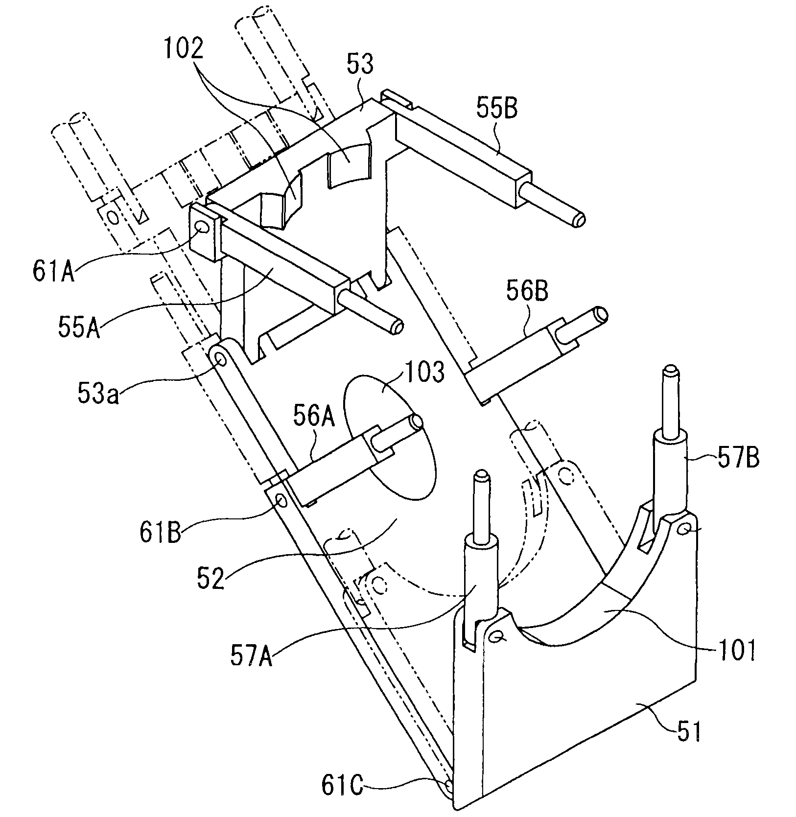
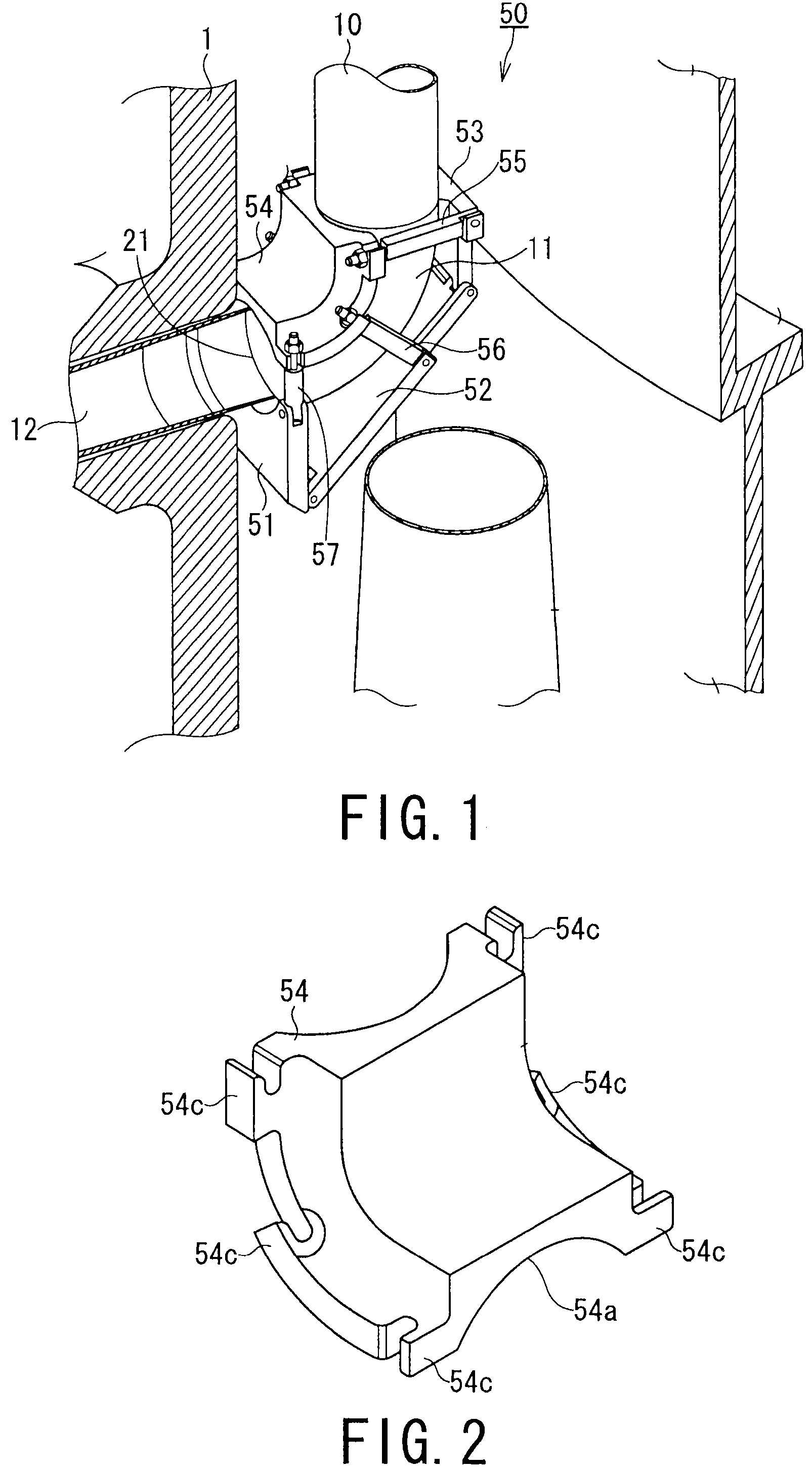
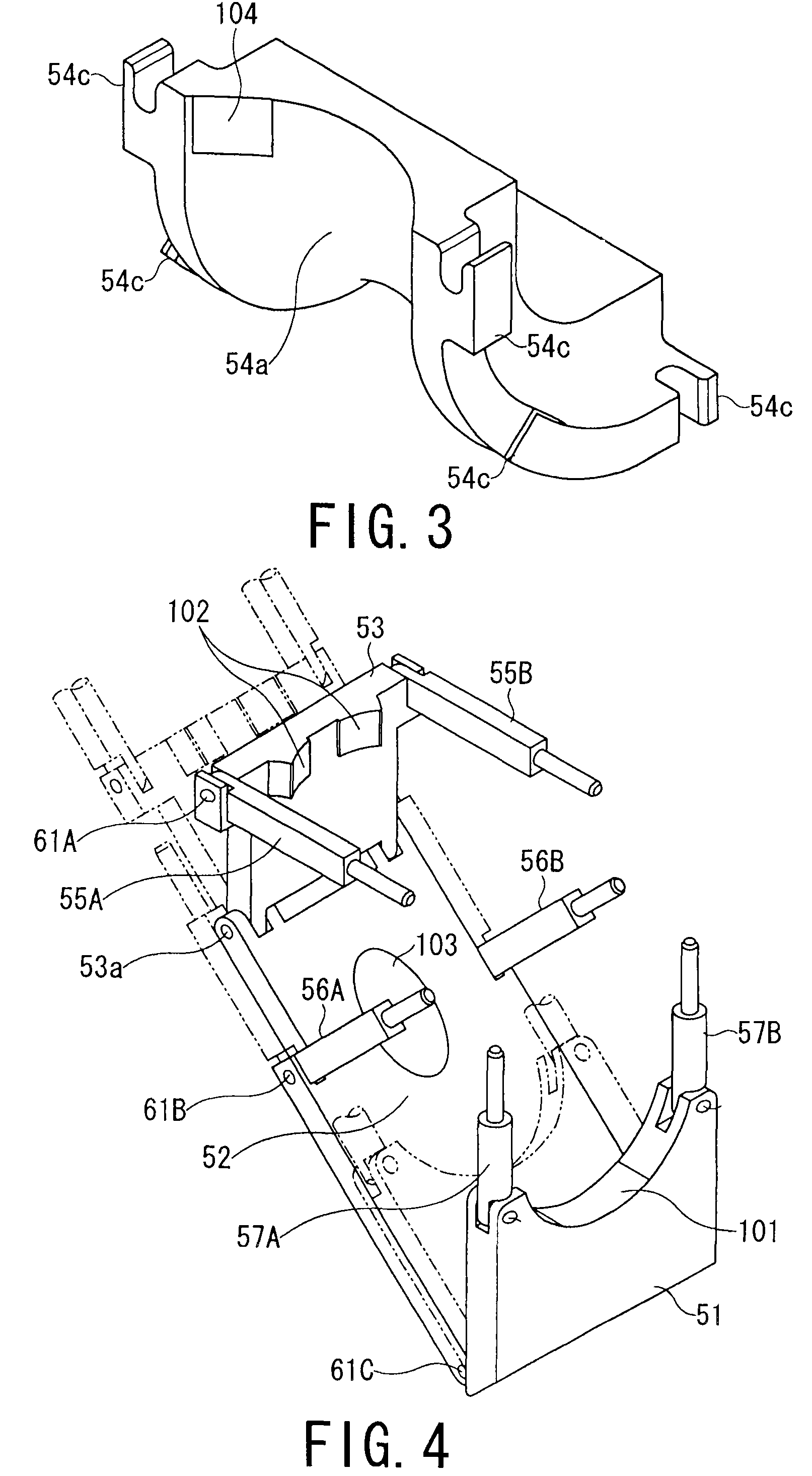
[0044]FIGS. 1 to 4 show the first embodiment of the present invention. FIG. 1 is a perspective view showing an overall structure and an installed state of a jet pump riser reinforcing apparatus according to the first embodiment of the present invention. FIGS. 2 and 3 are perspective views showing a structure of an elbow upper clamp of the jet pump riser reinforcing apparatus in different angles. FIG. 4 is a perspective view showing structures of an elbow lower clamping member, an elbow vertical portion clamping member, and an elbow horizontal portion clamping member.

[0045]As shown in FIG. 1, the riser reinforcing apparatus 50 of the present embodiment includes: an elbow upper clamp 54 for covering a riser elbow 11 from the upper side, the riser elbow 11 coupled to a thermal sleeve 12; an elbow lower portion clamp 52 as an elbow lower clamping member for clamping the riser elbow 11 from the lower side; a vertical portion clamp 53 as an elbow vertical portion clamping mem...

second embodiment (fig.5)

Second Embodiment (FIG. 5)

[0064]FIG. 5 is a perspective view showing an installed state of a jet pump riser reinforcing apparatus according to a second embodiment of the present invention. In this embodiment, the jet pump riser reinforcing apparatus includes an elbow lower clamping member, an elbow vertical portion clamping member, and an elbow horizontal portion clamping member, which are formed as a plurality of U-shaped members separated from each other.

[0065]This second embodiment is different from the first embodiment in shapes of the clamps to be mounted to the jet pump riser 10a, shapes of contact portions of the riser elbow upper clamp with coupling bolts, and differs in that the riser elbow lower portion clamp is not used.

[0066]In other words, in the embodiment, the clamps have the U-shapes and include bases 71A, 71B having contact portions in such shapes as to be fitted to the outer shapes of the riser pipe 10, and also include the thermal sleeve 12, arms 72A, 72B one ends...

third embodiment (

FIGS. 6 to 8)

[0070]FIGS. 6 to 8 show the third embodiment of the invention. FIG. 6 is a perspective view showing an installed state of a jet pump riser reinforcing apparatus according to a third embodiment of the present invention. FIG. 7 is a perspective view showing shapes of clamps. FIG. 8 is a perspective view showing an elbow upper clamp. In this third embodiment, a jet pump riser reinforcing apparatus includes the elbow lower clamping member, the elbow vertical portion clamping member, and the elbow horizontal portion clamping member, which are formed as a plurality of ring-shaped members separated from each other.

[0071]The embodiment is different from the first embodiment and the second embodiment in that the elbow upper clamp 88 to be mounted to the jet pump riser 10a is changed into a relatively simple structure.

[0072]In other words, as shown in FIGS. 6 and 7, the elbow upper clamp 88 of this embodiment has a structure in which a pair of clamp arms 82A, 82B having shapes of...


PUM


Abstract

An apparatus for reinforcing a jet pump riser includes: an elbow upper clamp for covering a riser elbow coupled to a thermal sleeve from an upper side thereof; an elbow lower clamping member for clamping the riser elbow from a lower side thereof; an elbow vertical portion clamping member for covering a vertical portion of the riser elbow; and an elbow horizontal portion clamping member for covering a horizontal portion of the riser elbow. These members are disposed in different orientations with respect to the elbow upper clamp so as to fix the thermal sleeve, the riser elbow and the riser pipe.

Description

BACKGROUND OF THE INVENTION[0001]1. Field of The Invention[0002]The present invention relates to an apparatus and a method for reinforcing a jet pump riser for preventing occurrence of a weld line crack of a jet pump riser fixed by being welded to an inside of a reactor pressure vessel of a boiling water reactor for preventing development of the crack that has occurred and for maintaining a function at the time of rupture of the weld line.[0003]2. Related Art[0004]Jet pumps in a boiling water reactor are disposed at an annular portion (downcomer portion) between a core shroud of a reactor pressure vessel (RPV) and an RPV inner wall and coupled to a recirculation system to circulate a coolant to a rector core.[0005]With reference to FIG. 10, a structure around the jet pump in the reactor pressure vessel 1 will be described schematically.[0006]As shown in FIG. 10, the jet pump 1a includes a riser 10a, an inlet mixer 9, a diffuser 13, and the like. The riser 10a includes a riser pipe 1...

Claims


Application Information

Patent Timeline
Patent Type & Authority Patents(United States)
IPC IPC(8): G21C23/00F16L43/00F16L3/00F16L17/00G21C19/00G21C9/00F16L33/16F16L21/00F16L3/08G21C19/28G21C15/00
CPCY02E30/40G21Y2002/206G21Y2004/301G21Y2002/303G21C15/25G21Y2002/104Y10T403/5761Y02E30/30G21C19/20G21C19/207G21D1/04
Inventor ABURA, MASAKAZUYASUDA, TOSHIHIROSUDO, KAZUOHATA, HARUHIKOKANAZAWA, YASUSHIKINUGASA, KUNIHIKOMORI, HAJIME
Owner KK TOSHIBA
Why Eureka
Try Eureka