
Methods for efficient state transition matrix based LFSR computations

a state transition matrix and computation method technology, applied in the field of computer processing, can solve the problems of inflexible hardware implementations, inability to deal with lfsr, and dated hardware implementations of lfsr's, and achieve enhanced lfsr computations, enhanced crc generation and checking methods and systems, and enhanced lfsr computations

Inactive Publication Date: 2014-05-06
INTEL CORP
View PDF3 Cites 0 Cited by
  • Summary
  • Abstract
  • Description
  • Claims
  • Application Information

AI Technical Summary

Benefits of technology

This patent is for a method and system to generate and check cyclic redundancy checks (CRCs) in data transmission. The technical effect of this invention is to improve the speed and efficiency of CRC generation and checking. In one case, the method uses a state transition matrix that can be expanded by adding additional rows to increase the size of the matrix. However, in another case, the output generating matrix is no longer needed for speedup. This allows for faster and more efficient data transmission.

Problems solved by technology

As communications systems become faster, however, traditional hardware implementations of LFSR's have become dated and require improvement.
Hardware implementations are not flexible because each LFSR needs to be mapped to a different hardware implementation.
Processors, however, are often ill-equipped to deal with LFSR.
However, this method is limited because there is an exponential increase in computational cost as the size of the lookup table increases.
While this approach can provide significant improvement in efficiency, it is still highly limited by the fixed data width of the processor.
As such, the potential speedup is limited, particularly when L (representing the number of state bits or length of the LFSR) approaches the data path width.
In addition, when the above matrix approach is implemented as a standalone hardware accelerator, matrix size is critical, as it directly relates to the complexity and cost, and therefore computing efficiency, of the implementation.

Method used


Image

  • Methods for efficient state transition matrix based LFSR computations
  • Methods for efficient state transition matrix based LFSR computations
  • Methods for efficient state transition matrix based LFSR computations

Examples


Embodiment Construction

[0025]The particular values and configurations discussed in these non-limiting examples can be varied and are cited merely to illustrate at least one embodiment and are not intended to limit the scope thereof.

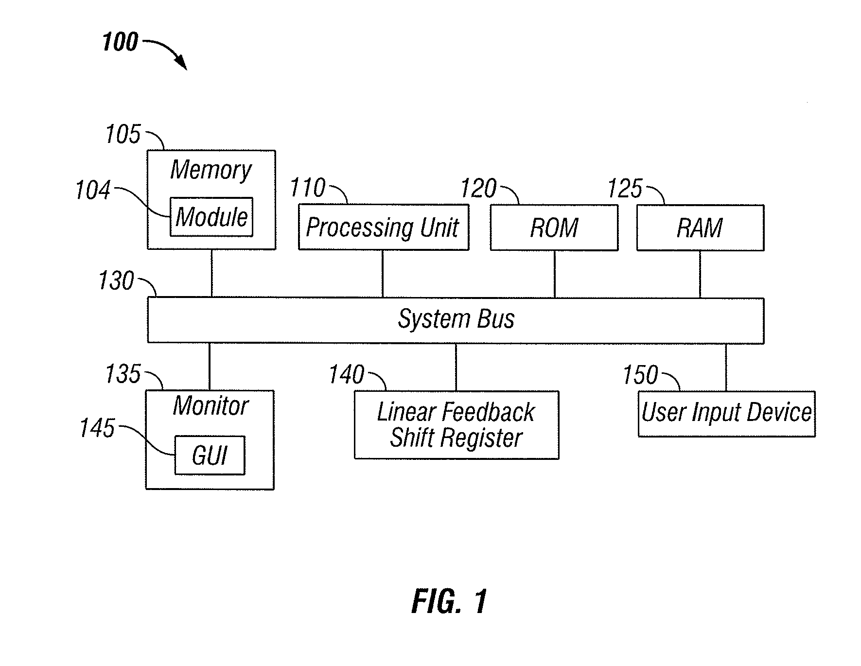
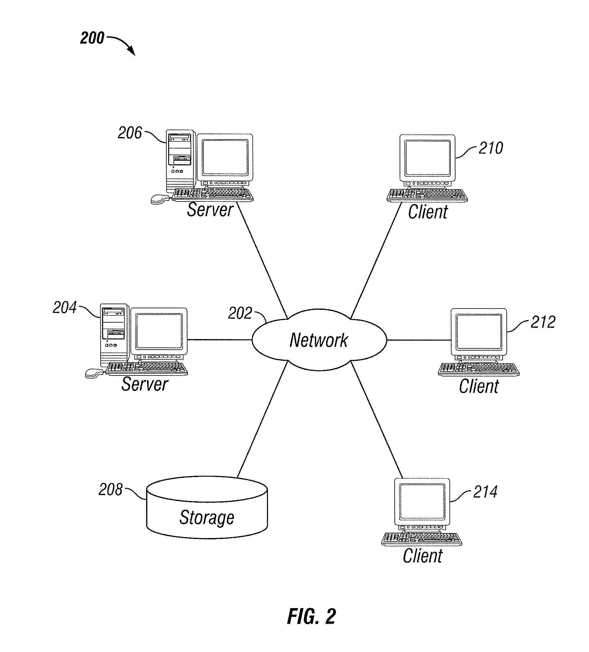
[0026]FIGS. 1 and 2 depict exemplary diagrams of data-processing environments in which embodiments of the present invention may be implemented. It should be appreciated that FIGS. 1 and 2 are only exemplary and are not intended to assert or imply any limitation with regard to the environments in which aspects or embodiments of the present invention may be implemented. Many modifications to the depicted environments may be made without departing from the spirit and scope of the present invention.

[0027]The embodiments described herein can be implemented in the context of a host operating system and one or more modules. Such modules may constitute hardware modules such as, for example, electronic components of a computer system. Such modules may also constitute software modules. I...


PUM


Abstract

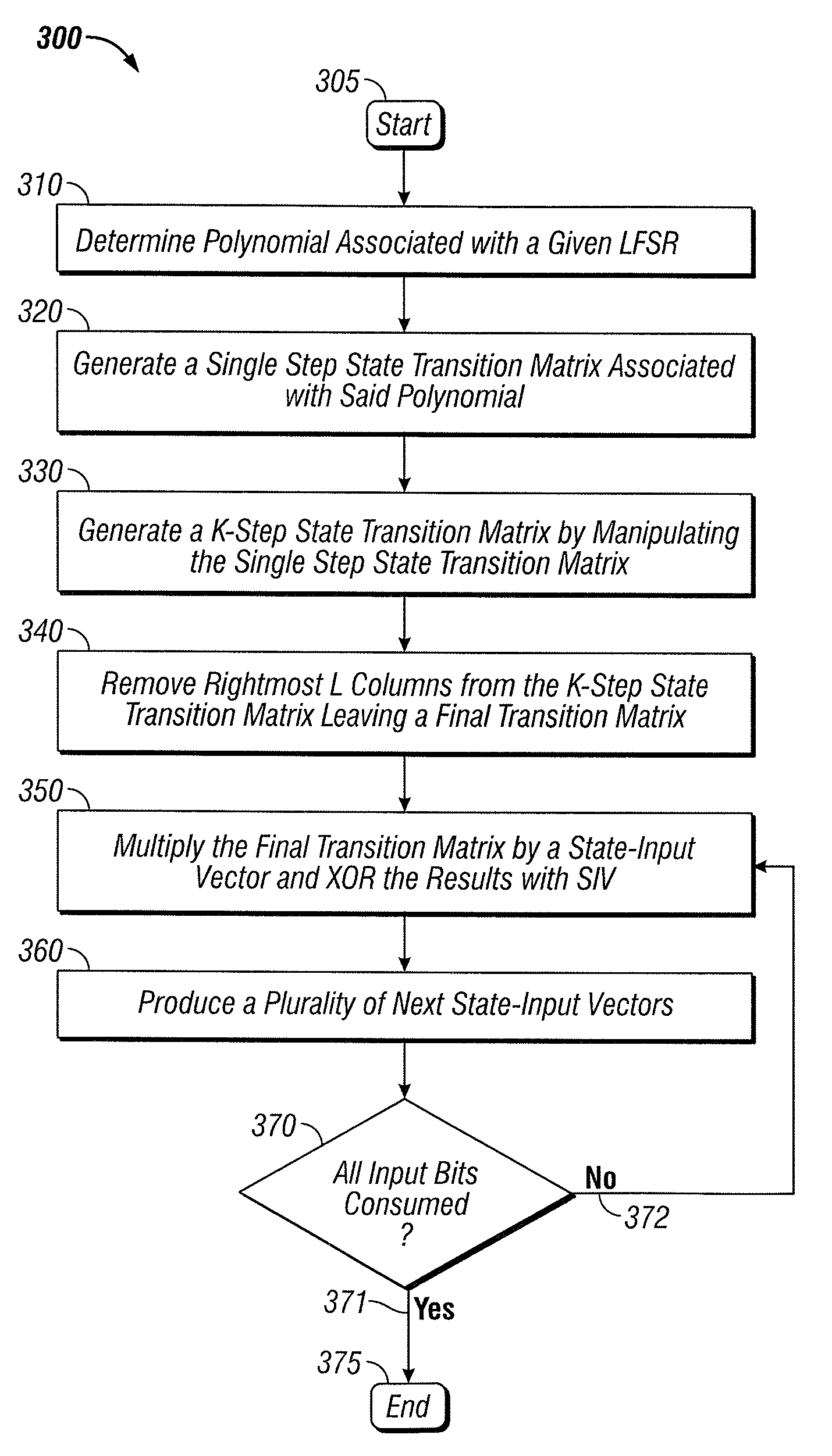
A method for efficient state transition matrix based LFSR computations are disclosed. A polynomial associated with a linear feedback shift register is defined. This polynomial is used to generate a single step state transition matrix. The single step state transition matrix is then modified into a more general k-step state transition matrix. The resultant combined matrix is reduced in size and can be multiplied by a state input vector, ultimately producing a plurality of next state-input vectors thereby providing improved efficiency in computing a LFSR.

Description

CROSS-REFERENCE TO PROVISIONAL APPLICATION[0001]This application claims the benefit of U.S. Provisional Patent Application Ser. No. 61 / 355,177, which was filed on Jun. 16, 2010 and entitled “Methods for Parallel Computation of Linear Sequential Circuits”. The above-referenced provisional patent application is incorporated herein by reference in its entirety.TECHNICAL FIELD[0002]Embodiments are generally related to the field of computer processing. Embodiments are also related to linear feedback shift registers and related components, methods, and systems. Embodiments are additionally related to the complementation of components such as scramblers, descramblers, cyclic redundancy devices, and turbo-encoding technologies. Embodiments are additionally related to state transition matrix technologies.BACKGROUND OF THE INVENTION[0003]A linear feedback shift register (LFSR) is commonly utilized for implementing components such as, for example, scramblers, descramblers, cyclic redundancy ch...

Claims


Application Information

Patent Timeline
Patent Type & Authority Patents(United States)
IPC IPC(8): G06F7/00
CPCH04L25/0226H04L25/0232H04L25/0212
Inventor YU, MENG-LIN
Owner INTEL CORP
Learn More