Method and system of framing components and hangers used in a structural interface

Inactive Publication Date: 2014-05-13
ROBELL GLENN
View PDF14 Cites 33 Cited by
  • Summary
  • Abstract
  • Description
  • Claims
  • Application Information

AI Technical Summary

Benefits of technology

[0009]The description herein provides preferred embodiments of the present invention but should not be construed as limiting its scope. For example, variations in the complexity, length, width, depth, and shape of the structure/detail made in the supporting beam; whether one or more sides/edges of a supporting beam receives structure/detail; whether the structure/detail used on the same or opposing sides/edges of an engineered wood beam framing component have the same or different configurations; the perimeter configuration of a hanger's top edge during use (whether substantially straight, angled/bent, folded, or shaped); whether a rib (welded or otherwise) is formed in the back of a hanger for insertion into structu

Problems solved by technology

However, at least three important disadvantages occur when traditional metal hangers are used.
A first disadvantage is that hanger layout and installation are often labor intensive, which increases construction cost.
The second disadvantage is that the design of prior art face-mounted hangers allows them to receive all of their strength from the fasteners/nails used to secure them to the framing components (which could, loosen over time as a result of sheering forces caused by weight/load transfer over a finished floor and/or the influence of strong/gale force winds against a roof).
The third disadvantage is that when prior art hangers are secured in part to the top of a supp

Method used


Image

  • Method and system of framing components and hangers used in a structural interface
  • Method and system of framing components and hangers used in a structural interface
  • Method and system of framing components and hangers used in a structural interface

Examples


Embodiment Construction

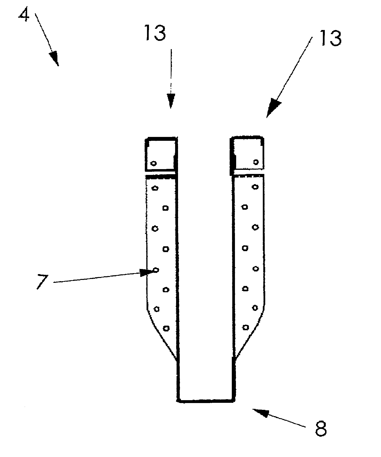
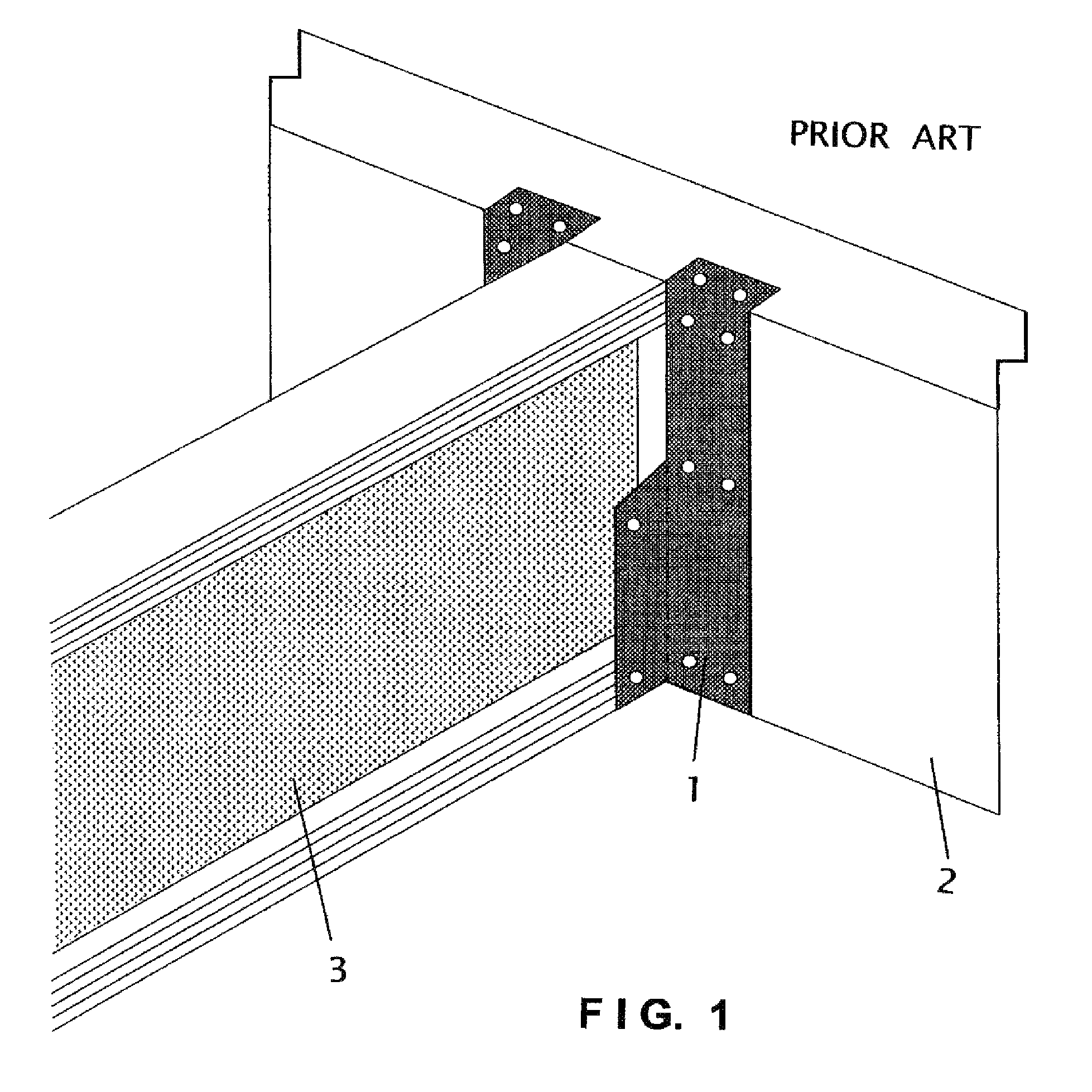
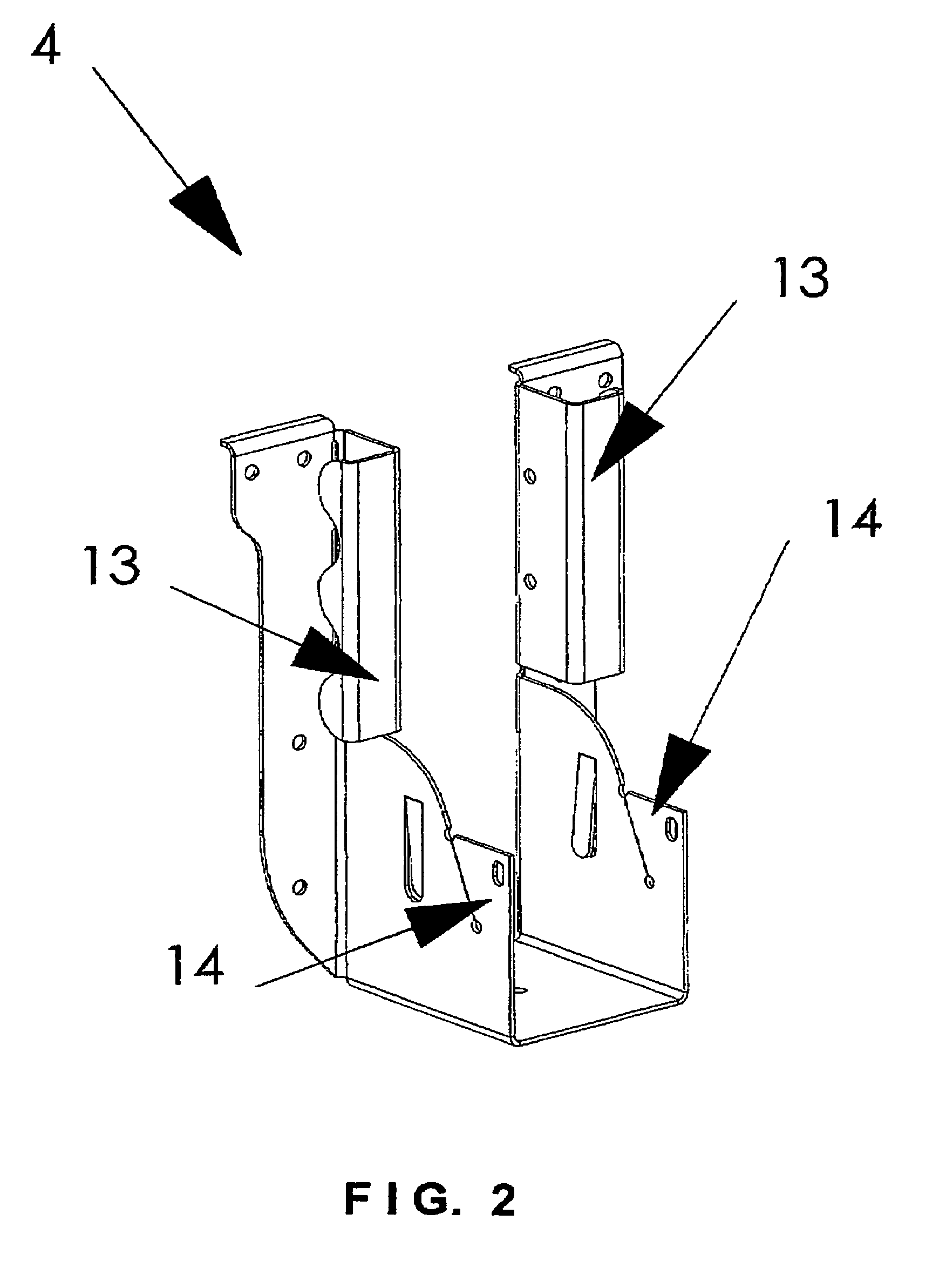
[0018]The present invention comprises a system and method intended for use in the residential and commercial construction of floors, ceilings, and roofs, and it provides structure / detail in the form of dato, grooves, cuts, cut-outs, and / or indentations 6 (hereinafter referred to as “indentations 6” without any intent of limitation) created by automated-feed equipment on at least one side / edge of framing components (such as supporting beam 2) during its manufacture, milling, and / or cutting to size at an off-site location prior to delivery to a worksite. The indentations 6 are configured for use with hangers that are preferably metal or plastic (such as the preferred present invention hangers 4 shown in FIGS. 2-8) in a structural interface (between supporting beam 2 and a supported joist / rafter 3) to provide the structural interface with significantly increased strength beyond that achievable by simply nailing hanger 4 to supporting beam 2. During its use to support hangers 4, the at ...


PUM


Abstract

A system and method used in residential and commercial construction of floors, ceilings and roofs, where a beam and hanger together support a joist/rafter to which sheathing is applied. Hanger design features include bendable stiffeners that provide pinching structural support for opposing sides of an engineered wood I-joist web after the joist/rafter is seated into the bridge of the hanger, providing a superior structural interface connection, less material cost, and no contact between the hanger and sheathing which reduces unwanted noise in finished construction. Additional strengthening of the structural/load-bearing interface between the joist/rafter and beam may include selected horizontally-extending dato, groove, cut, or other detail formed in the support beams during their manufacture/milling and rearwardly-extending protections on the hanger configured to engage the detail.

Description

CROSS-REFERENCES TO RELATED APPLICATIONS[0001]This U.S. utility patent application relates to the previously filed and still pending U.S. provisional patent application filed by the same inventor herein and having the title of System and Method of Interlocking Framing Connectors into Engineered Wood Framing Components and Solid Sawn Lumber, the application number of 61 / 227,770, and a filing date of 22 Jul. 2009. As a result, domestic priority based upon this above-mentioned U.S. provisional patent application is requested for the new U.S. utility patent application now being filed.BACKGROUND[0002]1. Field of the Invention[0003]This invention relates to the field of wood framing products and methods of their connection in structural interfaces using hangers, specifically to a system and method of providing supporting beams and supported joists / rafters for use in a load-bearing structural interface upon which sheathing is eventually secured, in combination with a hanger that does not ...

Claims


Application Information

Patent Timeline
IPC IPC(8): E04C5/00E04B1/38
CPCE04B5/14E04C3/14E04B1/2612E04B1/38
Inventor ROBELL, GLENN
Owner ROBELL GLENN
Why Eureka
Try Eureka