Imaging system simulator

a simulator and imaging system technology, applied in the field of medical science, can solve the problems of ineffective current approaches, unsuitable for children's use, and inconvenient ct scan process, and achieve the effects of reducing patient anxiety, simplifying function and purpose presentation, and facilitating effective patient education

Active Publication Date: 2014-05-13
KONINK PHILIPS ELECTRONICS NV
View PDF15 Cites 14 Cited by
  • Summary
  • Abstract
  • Description
  • Claims
  • Application Information

AI Technical Summary

Benefits of technology

[0010]Another advantage resides in simplified presentation of function and purpose of an imaging system.
[0011]Another advantage resides in interactive presentation of function and purpose of an imaging system.
[0012]Still further advantages and benefits of the present invention will become apparent to those of ordinary skill in the art upon reading and understanding the following detailed description of the preferred embodiments.

Problems solved by technology

A CT scan is often an uncomfortable process for most people, especially young children.
The known ultrasound training systems are not appropriate for children.
In summary, the current approaches are not universal and not effective.
In many cases, the unfamiliarity with the environment and lack of knowledge of the actual scanning process increases patient's anxiety which might lead to cancellations of scheduled scanning sessions with a corresponding financial impact on the health care providers.

Method used


Image

  • Imaging system simulator
  • Imaging system simulator
  • Imaging system simulator

Examples


Embodiment Construction

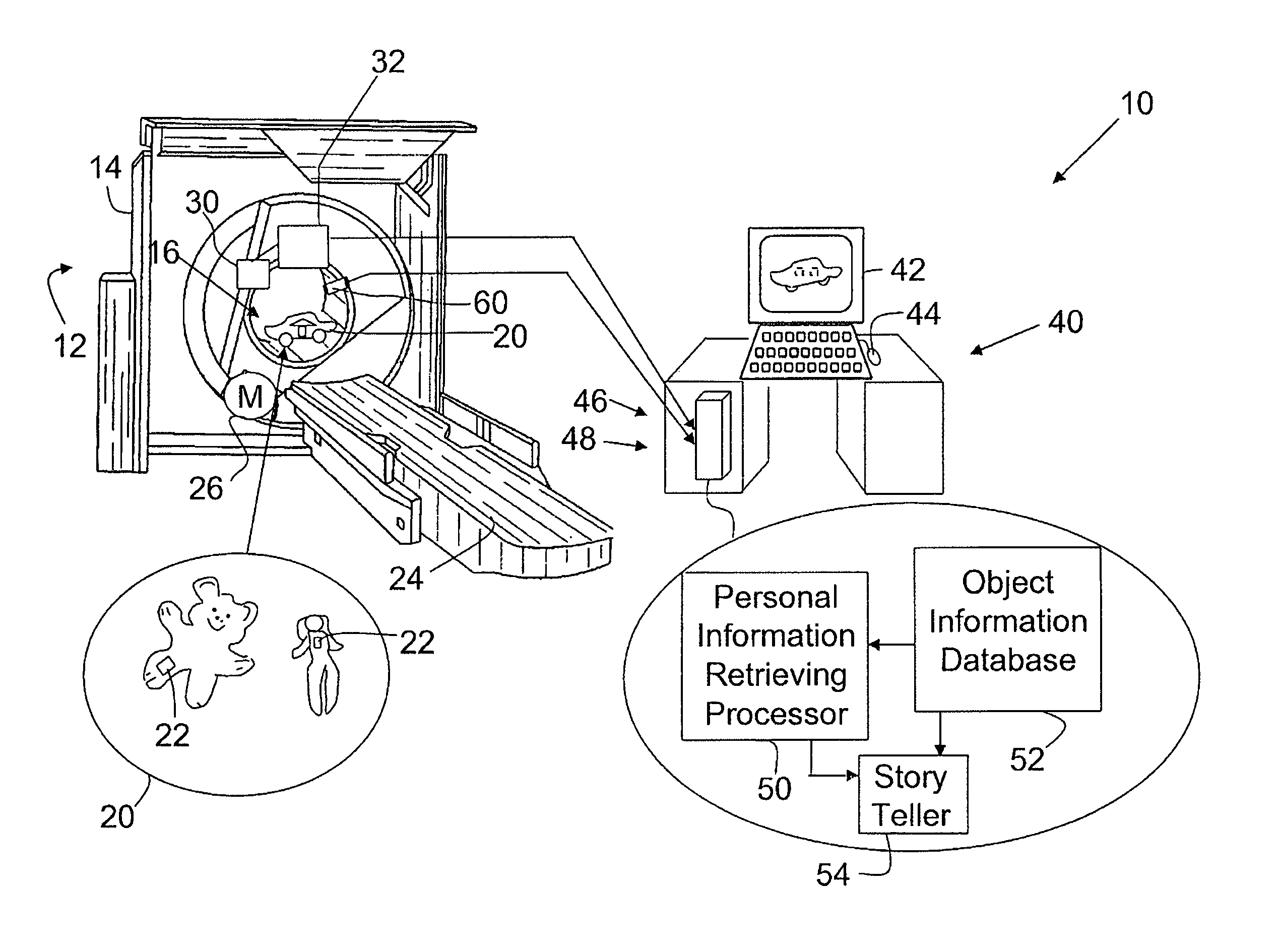
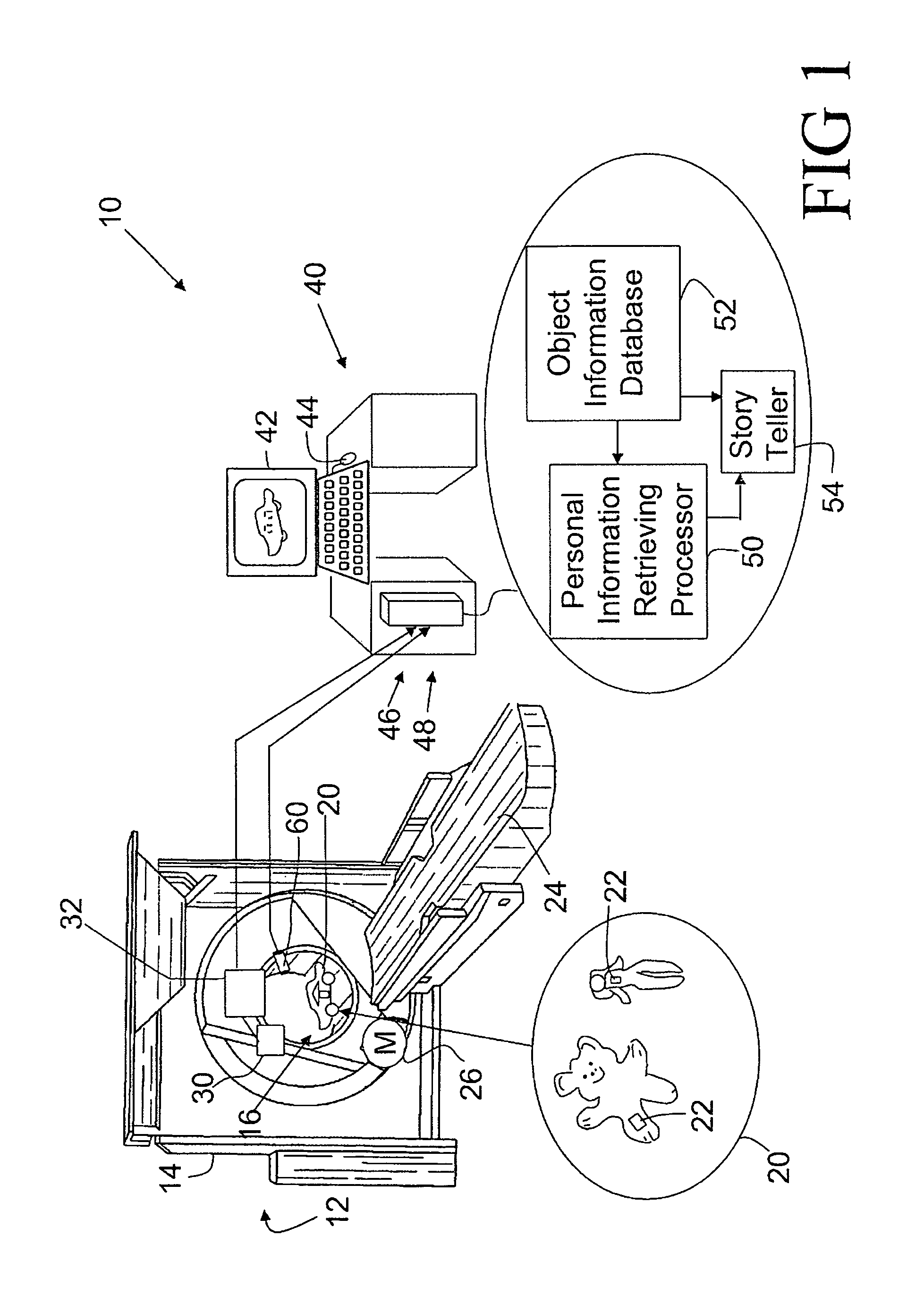
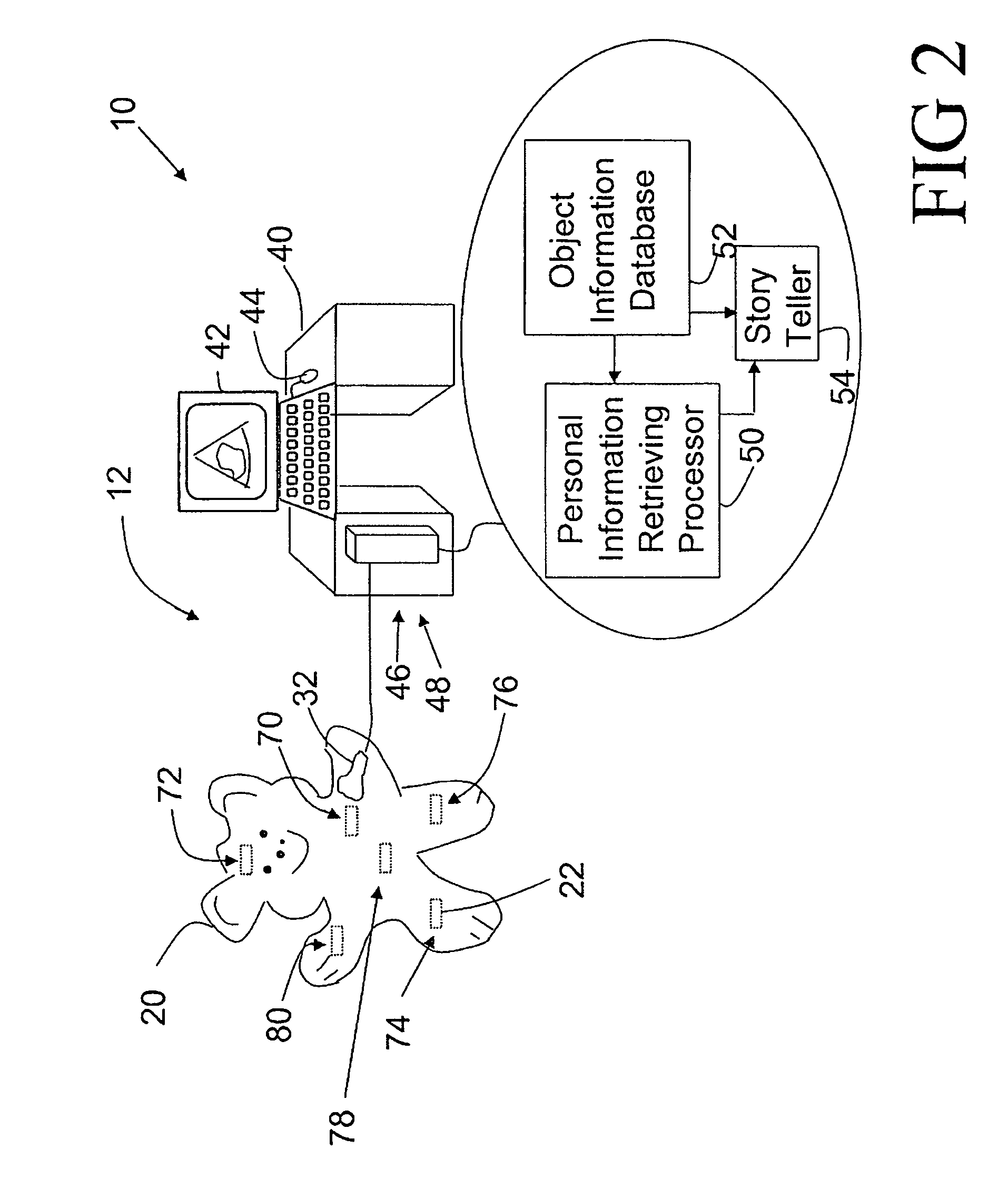
[0016]With reference to FIG. 1, an imaging simulation system 10 includes a scaled model of a diagnostic imaging scanner or simulator 12 to effectively explain the imaging procedure to the patients. The simulator 12 includes many like parts to a real diagnostic scanner, such as a CT scanner, MRI simulator, SPECT simulator, PET simulator, ultrasound simulator, and other imaging simulators. For example, the simulator 12 includes a non-rotating gantry 14. A bore 16 defines an examination region of the simulator 12. A plurality of objects 20 such as toys is each identified with an identification (ID) tag 22 encoded with a unique identification code. The ID tag 22, for example, can be an RFID chip, a color tag, a shape tag, an RF tag, and other appropriately identifiable tag. The ID tag 22 is embedded or otherwise associated with each object 20. The toys 20 are made of an appropriate size and material which is appropriate for use with the simulator 12. A selected object 20 is positioned o...


PUM


Abstract

A medical training and simulation system includes a plurality of inanimate objects, each being associated with an identification tag which stores an identification code which uniquely identifies an associated object. A database stores information of the objects. A reader reads a respective identification code of a selected object. An information retrieving processor retrieves the stored information which corresponds to the read identification code of the selected object. A device reproduces at least a portion of the retrieved information of the selected object.

Description

CROSS REFERENCE TO RELATED APPLICATIONS[0001]This application claims the benefit of U.S. provisional application Ser. No. 60 / 704,023 filed Jul. 29, 2005, which is incorporated herein by reference.BACKGROUND OF THE INVENTION[0002]The following relates to medical arts. It finds particular application in conjunction with computed tomography (CT) simulations and will be described with particular reference thereto. However, it finds application in simulating other types of imaging, such as single photon emission computed tomography (SPECT), positron emission tomography (PET), three-dimensional x-ray imaging, ultrasound imaging, magnetic resonance imaging (MRI), and the like.[0003]In general, a computed-tomography system comprises an x-ray source and an x-ray detector which rotates around a subject to be examined. From several orientations, the subject is irradiated with an x-ray beam from the x-ray source. The x-ray detector receives x-radiation that has passed through the subject at the...

Claims


Application Information

Patent Timeline
Patent Type & Authority Patents(United States)
IPC IPC(8): A63H30/00A63H30/04A63H30/02G09B3/00G09B23/24G09B23/28G09B5/00A63H3/28G09B19/00G09B25/00G09B7/00G09B5/04
CPCG09B5/00A63H3/28A63H30/00A63H30/04G09B5/04G09B25/00G09B23/28G09B3/00G09B23/24G09B19/00G09B7/00G09B23/286A63H30/02
Inventor MARMAROPOULOS, GEORGEVU, GIANG T.HERCZEGH, LASZLOJANSEN, JOHNPARAMESWARAN, LEKSHMY
Owner KONINK PHILIPS ELECTRONICS NV
Why Eureka
Try Eureka