Magnetic device with high saturation current and low core loss

low core loss technology, applied in the direction of transformer/inductance magnetic core, inductance, magnetic body, etc., can solve the problem that the choke cannot produce the desired output at a high saturation current, the manufacturing cost of a traditional choke is high, and the choke is more and more difficult to manually wind the wire. to achieve the effect of low cost, low core loss and high saturation curren

Active Publication Date: 2014-05-13
CYNTEC
View PDF15 Cites 80 Cited by
  • Summary
  • Abstract
  • Description
  • Claims
  • Application Information

AI Technical Summary

Benefits of technology

[0011]Accordingly, it is an object of the present invention to provide a low cost, compact magnetic device with high saturation current at heavy load and low core loss at light load.

Problems solved by technology

However, a traditional choke with a toroidal core requires manual winding of the wire coil onto the toroidal core.
Therefore, the manufacturing cost of a traditional choke is high due to the high labor cost.
Recent trends to produce increasingly powerful, yet smaller chokes have led to numerous challenges to the electronics industry.
In particular, when the size of a traditional choke with a toroidal core is reduced to a certain extent, it becomes more and more difficult to manually wind the wire coil onto the smaller toroidal core, and the choke can no longer produce a desired output at a high saturation current.
However, the sealed choke cannot produce a desired output at a high saturation current.
In addition, it also becomes more and more difficult to wind the wire coil onto the ferrite core when the size of the sealed choke shrinks to a certain extent.
However, the iron-powder core has a relatively high core loss.
In addition, since the wire coil is placed in the mold during the molding process and the wire coil cannot sustain high temperature, it is not possible to perform an annealing process to reduce the core loss of the molded core after the molding process.

Method used


Image

  • Magnetic device with high saturation current and low core loss
  • Magnetic device with high saturation current and low core loss
  • Magnetic device with high saturation current and low core loss

Examples


Embodiment Construction

[0026]The present invention will now be described in detail with reference to the accompanying drawings, wherein the same reference numerals will be used to identify the same or similar elements throughout the several views. It should be noted that the drawings should be viewed in the direction of orientation of the reference numerals.

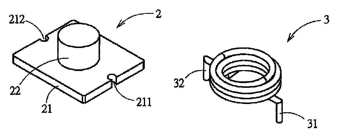
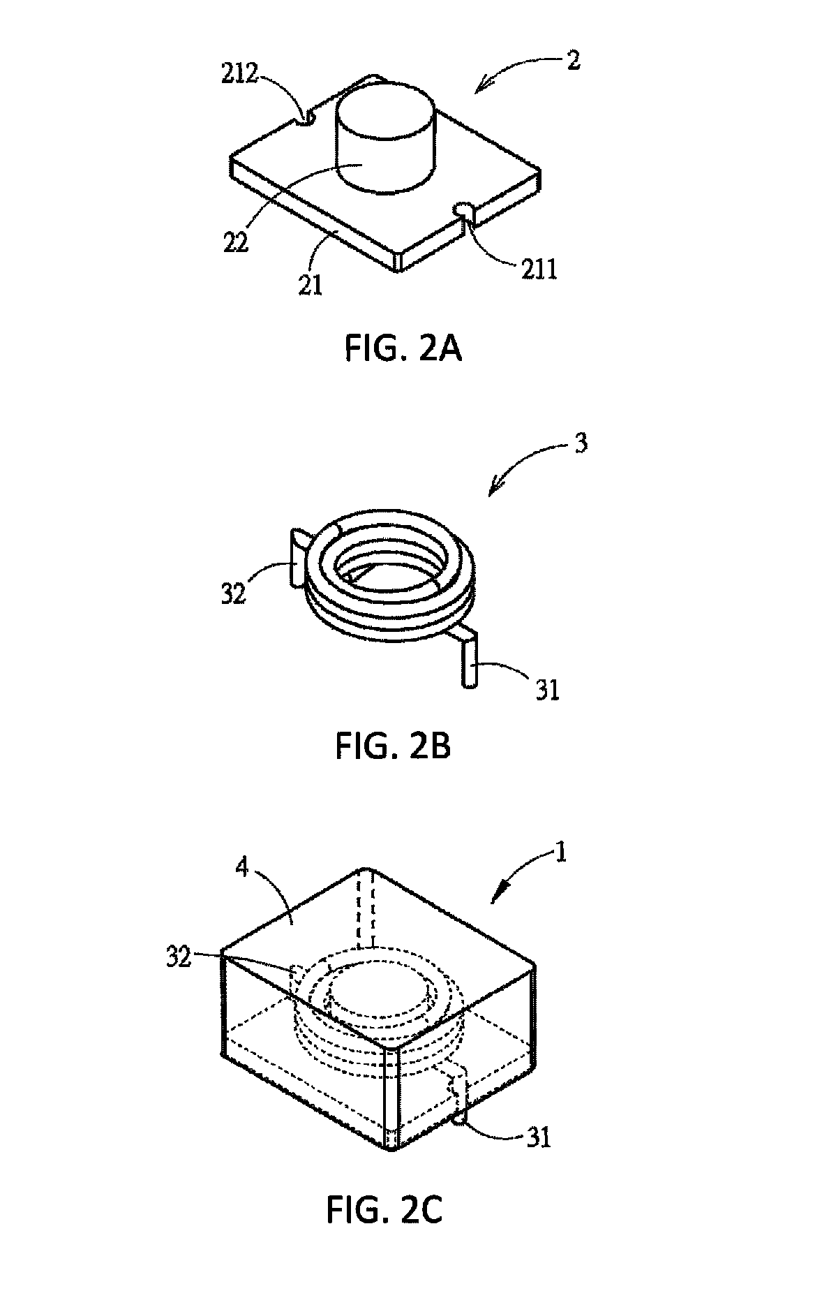
[0027]FIGS. 2A-2C is a perspective view of a choke in accordance with an embodiment of the present invention. As embodied in FIGS. 2A-2C, the choke 1 as a magnetic device comprises a T-shaped magnetic core 2, a wire coil 3 and a magnetic body 4. The T-shaped magnetic core 2 includes a base 21 and a pillar 22. The base 21 has a first / top surface and a second / bottom surface opposite to the first / top surface. The pillar 22 is located on the first / top surface of the base 21. The second / bottom surface of the base 21 is exposed to the outer environment as an outer surface of the choke 1. The wire coil 3 forms a hollow part for accommodating the pillar 22 suc...


PUM

PropertyMeasurementUnit
core lossaaaaaaaaaa
magnetic fieldaaaaaaaaaa
magnetic flux densityaaaaaaaaaa

Abstract

A magnetic device includes a T-shaped magnetic core, a wire coil and a magnetic body. The T-shaped magnetic core includes a base and a pillar, and is made of an annealed soft magnetic metal material, a core loss PCL (mW/cm3) of the T-shaped magnetic core satisfying: 0.64×f0.95×Bm2.20≦PCL≦7.26×f1.41×Bm1.08, where f (kHz) represents a frequency of a magnetic field applied to the T-shaped magnetic core, and Bm (kGauss) represents the operating magnetic flux density of the magnetic field at the frequency. The magnetic body fully covers the pillar, any part of the base that is located above the bottom surface of the base, and any part of the wire coil that is located directly above the top surface of the base.

Description

CROSS-REFERENCE TO RELATED APPLICATIONS[0001]N / ABACKGROUND OF THE INVENTION[0002]1. Field of the Invention[0003]The present invention relates to a magnetic device, and more particularly to a choke with high saturation current and low core loss.[0004]2. Background of the Invention[0005]A choke is one type of magnetic device used for stabilizing a circuit current to achieve a noise filtering effect, and a function thereof is similar to that of a capacitor, by which stabilization of the current is adjusted by storing and releasing electrical energy of the circuit. Compared to the capacitor that stores the electrical energy by an electrical field (electric charge), the choke stores the same by a magnetic field.[0006]FIG. 1A illustrates a conventional choke with a toroidal core. However, a traditional choke with a toroidal core requires manual winding of the wire coil onto the toroidal core. Therefore, the manufacturing cost of a traditional choke is high due to the high labor cost.[0007...

Claims


Application Information

Patent Timeline
Patent Type & Authority Patents(United States)
IPC IPC(8): H01F27/24H01F27/28H01F27/02H01F17/04
CPCH01F27/02H01F27/28H01F17/04H01F27/29H01F27/24H01F17/045H01F27/255H01F27/2828H01F1/14741H01F1/14766H01F1/14791H01F27/022
Inventor LIU, CHUN-TIAOHSIEH, LAN-CHINWU, TSUNG-CHANLEE, CHI-HSUNCHUANG, CHIH-SIANG
Owner CYNTEC
Why Eureka
Try Eureka