Method and system for automatically establishing a component description format (CDF) debugging environment

a component description and debugging environment technology, applied in the field of automatic setting a user-friendly environment, can solve the problems of increasing the interoperability demand of designers, design houses, and support products, and complicating abstractions, and reducing the overall eda design flow. cost and time-consuming and time-consuming

Active Publication Date: 2014-05-13
CADENCE DESIGN SYST INC
View PDF2 Cites 20 Cited by
  • Summary
  • Abstract
  • Description
  • Claims
  • Application Information

AI Technical Summary

Problems solved by technology

As electronic design automation (EDA) and circuit design is becoming more and more intricate and complex, the demand for interoperability of designers, design houses, and support products is increasing.
While this may seem a trivial matter, many factors, layers, and abstractions complicate the matter.
Such distractions can prove costly and time consuming in the overall EDA design flow, especially considering the iterative nature of such a design flow.

Method used


Image

  • Method and system for automatically establishing a component description format (CDF) debugging environment
  • Method and system for automatically establishing a component description format (CDF) debugging environment
  • Method and system for automatically establishing a component description format (CDF) debugging environment

Examples


Embodiment Construction

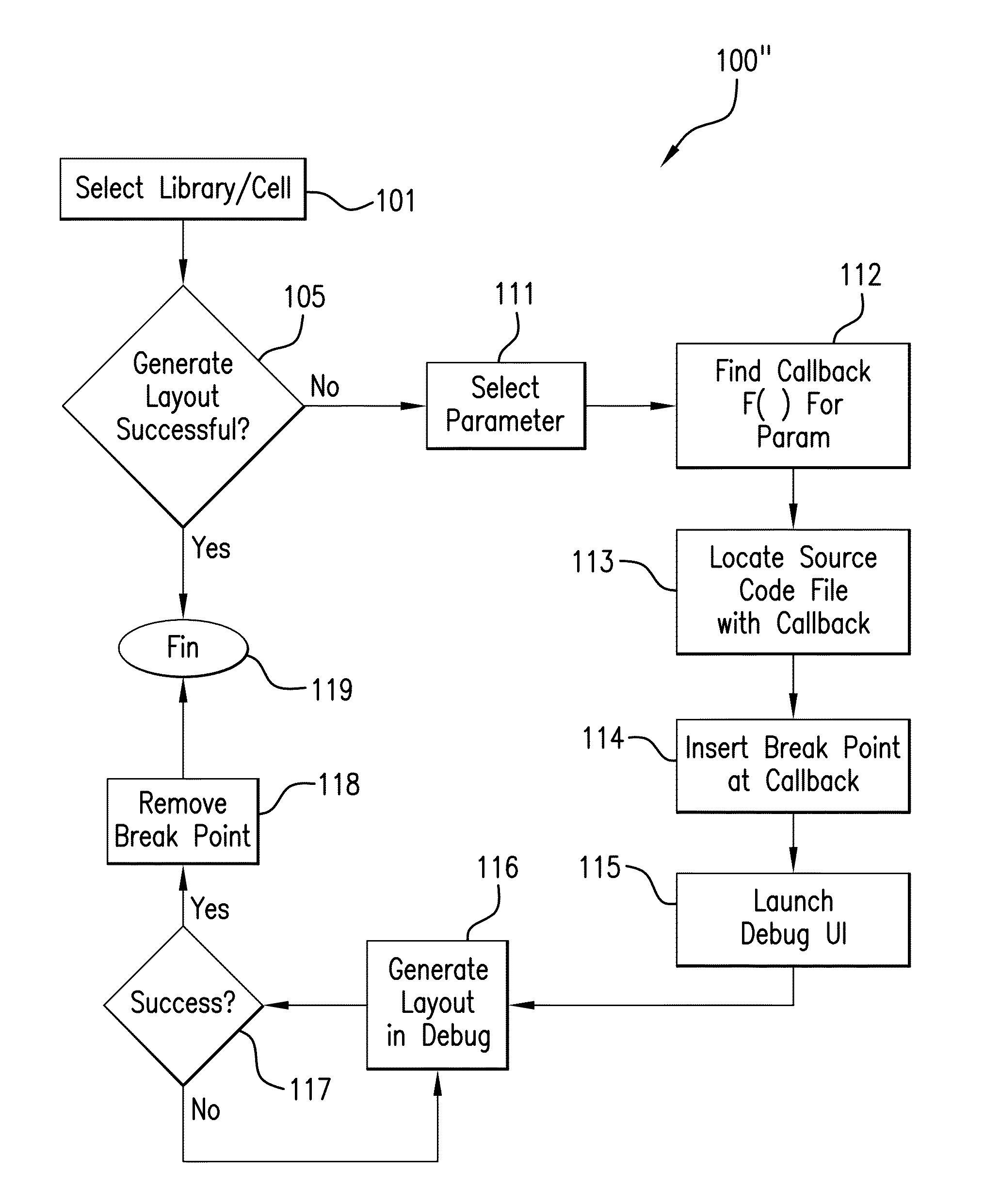
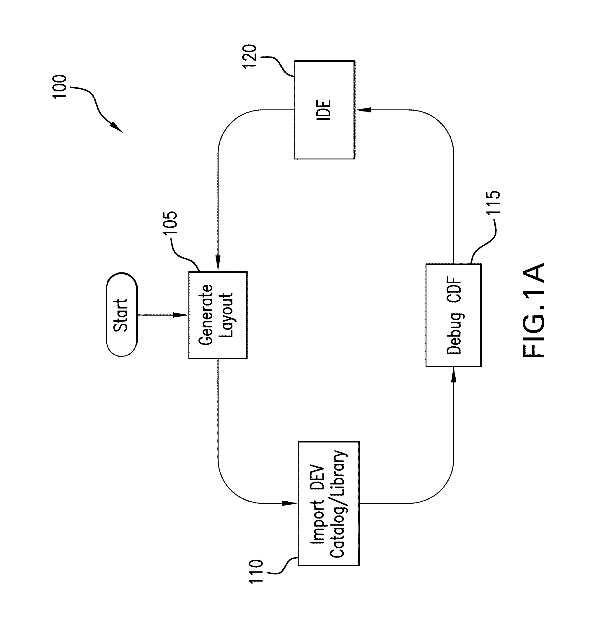
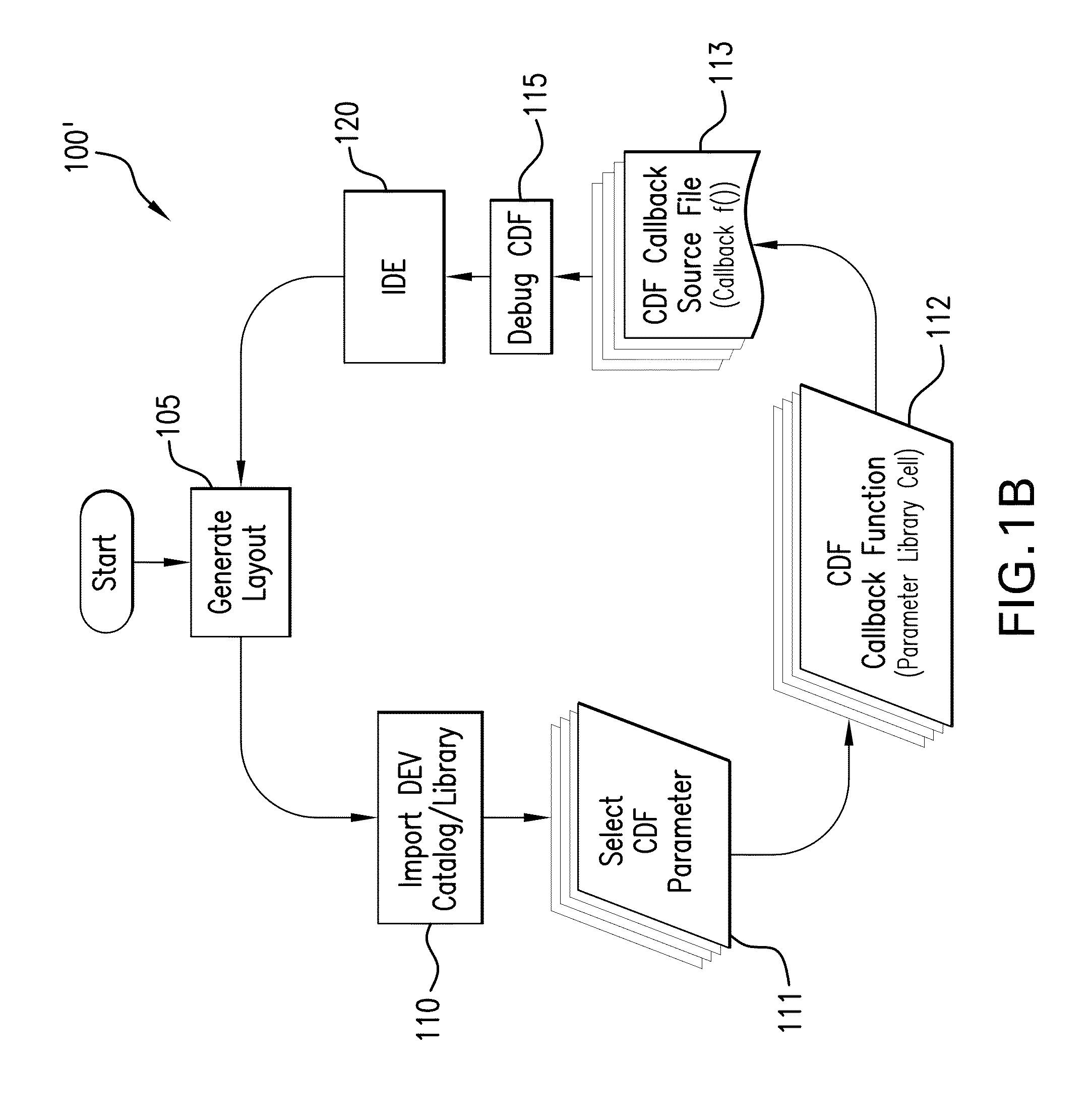
[0029]Reference will now be made in detail to the embodiments of the present general inventive concept, examples of which are illustrated in the accompanying drawings, wherein like reference numerals refer to the like elements throughout. It is to be understood that the term invention, when used herein, refers to the general inventive concept underlying the exemplary embodiments described below, and that the inventive concept is not limited to such illustrative embodiments themselves.

[0030]Systems, components, integrated circuits (ICs), and the like, may be modeled in a variety of different ways in an electronic design automation flow. For example, some of the ways of modeling a system include a merely logical schematic diagram which omits all physical characteristics or dimensionality and merely shows simplified or abstracted representations of components or cells within the device. Another manner of representing a system is a physical layout which shows an almost fully elaborated ...


PUM


Abstract

A system and method are provided for establishing a debugging environment in an Electronic Design Automation work-flow. A user-interface is provided for interfacing with users by displaying a list of debuggable parameters, accepting a selection thereof, and automatically locating both the callback function which sets the selected parameter, and the source code file which contains the callback function. Additionally, it is determined whether the callback function sets solely the selected parameter, or several different parameters, and an automatic breakpoint is set accordingly to break only responsive to the selected parameter. On execution of the modified callback function, execution will be arrested by the automatically-set intelligent breakpoint and a debugging user-interface will be generated for the user to display the relevant source code, callback function, parameter names and values, system state, and the like. Upon completion of the debugging process, the automatically-set breakpoint will be removed.

Description

BACKGROUND OF THE INVENTION[0001]The subject system and method are generally directed to automatically establishing a user-friendly, efficient, and effective debugging environment for electronic design automation (EDA) software environments. The system and method provide automated measures for interacting with a developer, automatically locating both a source file and a specific callback function to be debugged responsive to a developer merely selecting a parameter. The system and method automatically map and determine which source file and which callback function are implicated by the indicated parameter. Once the correct callback function and source code files are located, automatic break points may be set to provide a debugging environment for the user with merely the indication of the single parameter. The system and method thereby enable and provide an automated debugging environment for process design kit (PDK), Open PDK, interoperable PDK (iPDK), and / or PCell library / Pycell l...

Claims


Application Information

Patent Timeline
Patent Type & Authority Patents(United States)
IPC IPC(8): G06F17/50G06F9/455
CPCG06F17/50G06F11/362G06F17/5068G06F9/455G06F11/3664G06F2217/14G06F30/333G06F30/39G06F11/3636
Inventor LAMANT, GILLES S. C.TING, LI-CHIENCALUYA, SERENA CHIANGCHEN, CHIA-FU
Owner CADENCE DESIGN SYST INC
Why Eureka
Try Eureka