Backlight module

a backlight module and module technology, applied in the field of backlight modules, can solve the problems of reducing heat dissipation performance, increasing processing cost, and severely affecting heat dissipation performance, and achieve the effects of ensuring temperature uniformity of backboards, automatic adjustment of thermal conductivity, and facilitating control of light bars

Active Publication Date: 2014-05-20
TCL CHINA STAR OPTOELECTRONICS TECH CO LTD
View PDF8 Cites 2 Cited by
  • Summary
  • Abstract
  • Description
  • Claims
  • Application Information

AI Technical Summary

Benefits of technology

[0007]An objective of the present invention is to provide a backlight module, which uses thermo-sensitive heat conduction material to automatically adjust thermal conductivity so as to facilitate control of temperature of light bars within a predetermined range thereby ensuring temperature uniformity of backboard.
[0015]The efficacy of the present invention is that the present invention provides a backlight module, which comprises a thermo-sensitive heat conduction material interposed between a light bar and a backboard or between the light bar and a bracket. The thermo-sensitive heat conduction material functions to automatically adjust thermal conductivity coefficient with variation of temperature so that different thermal conductivity coefficients are realized at different sites of the light bar in order to control the temperature of the whole light bar in a predetermined range to ensure desired performance of thermal conduction and further ensuring temperature uniformity of the whole backlight module and preventing the occurrence of luminance lowering of the whole backlight module due to excessive local high temperature. Further, the filling of the thermo-sensitive heat conduction material make the contact engagement between the light bar and the backboard or between the light bar and the bracket more tight thereby eliminating the need of special processing of the bracket that is required in the prior art so that the cost can be reduced.

Problems solved by technology

Fastening is often done with bolt or heat dissipative adhesive tapes, of which the former may easily cause air thermal resistance between the light bar and the bracket, leading to reduced heat dissipation performance, while the later has low coefficient of thermal conductivity, which severely affects the performance of heat dissipation.
However, this surely brings a consequence of increasing processing cost.
However, such a technical solution increases the cost of the LED backlight module to quite an extent and the number of structural components is great, making the assembling tedious and defect rate of assembling increased.

Method used


Image

  • Backlight module
  • Backlight module
  • Backlight module

Examples


Embodiment Construction

[0022]To further expound the technical solution adopted in the present invention and the advantages thereof, a detailed description is given to preferred embodiments of the present invention and the attached drawings.

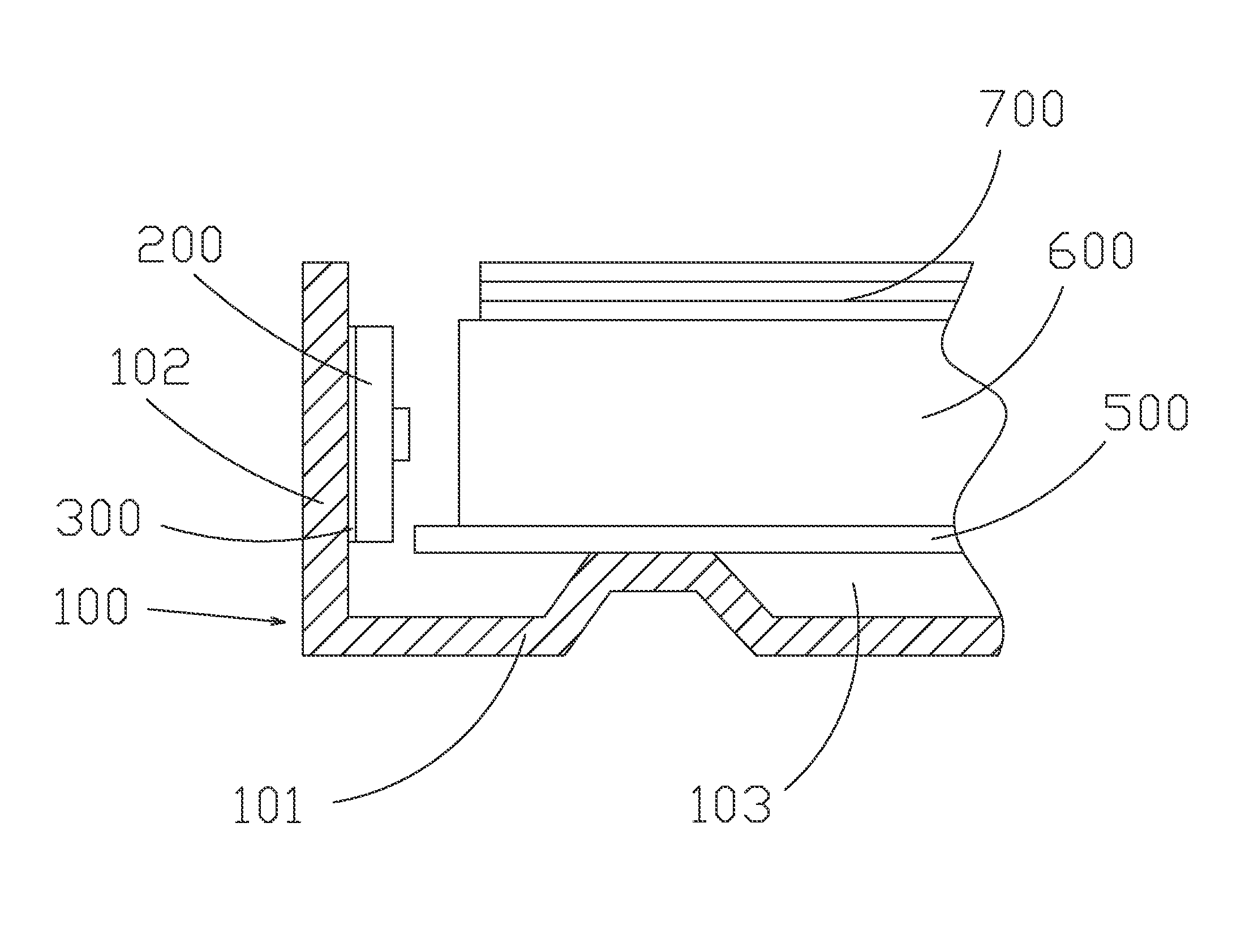
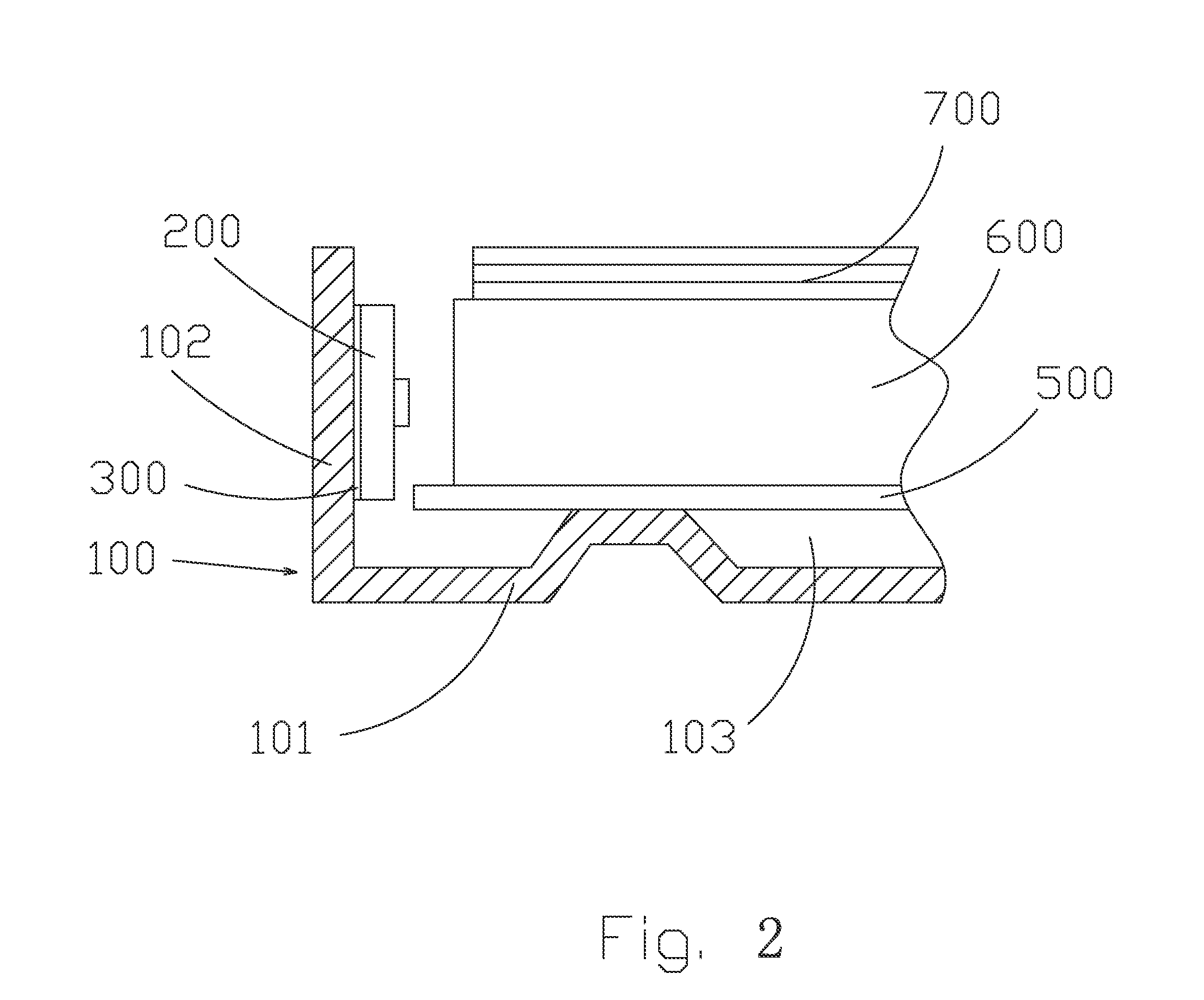
[0023]With reference to FIGS. 2 and 3, schematic views are given to show a backlight module according to an embodiment of the present invention. The backlight module of the present invention comprises: a backboard 100, a light bar 200 mounted inside the backboard 100, a thermo-sensitive heat conduction material 300 arranged between the backboard 100 and the light bar 200, a reflection plate 500 mounted inside the backboard 100, a light guide board 600 arranged on the reflection plate 500, and optic components 700 arranged on the light guide board 600. The light bar 200 emits light that transmits, directly or after being reflected by the reflection plate 500, into the light guide board 600 to thereby provide a planar light source of homogeneous brightness for the optic c...


PUM


Abstract

The present invention provides a backlight module, which includes a backboard, a light bar mounted on the backboard, and a thermo-sensitive heat conduction material interposed between the backboard and the light bar. The thermo-sensitive heat conduction material functions to automatically adjust thermal conductivity coefficient with variation of temperature so that different portions of the light bar have different thermal conductivity coefficients in order to control the temperature of the whole light bar in a predetermined range to ensure desired performance of thermal conduction and further ensuring temperature uniformity of the whole backlight module and preventing the occurrence of luminance lowering of the whole backlight module due to excessive local high temperature.

Description

BACKGROUND OF THE INVENTION[0001]1. Field of the Invention[0002]The present invention relates to the technical field of liquid crystal displaying, and in particular to a backlight module that provides excellent thermal conductivity.[0003]2. The Related Arts[0004]Liquid crystal display (LCD) has a variety of advantages, such as compact device size, low power consumption, and being free of radiation, and is thus widely used. Most of the LCDs that are currently available in the market are backlighting LCDs, which comprise a liquid crystal panel and a backlight module. The working principle of the liquid crystal panel is that liquid crystal molecules interposed between two parallel glass plates and a plurality of vertical and horizontal fine electrical wires is arranged between the two glass plates, whereby the liquid crystal molecules are controlled to change direction by application of electricity to refract light emitting from the backlight module for generating images. Since the liq...

Claims


Application Information

Patent Timeline
Patent Type & Authority Patents(United States)
IPC IPC(8): F21V29/00
CPCG09F13/18G09F2013/222
Inventor YU, GANG
Owner TCL CHINA STAR OPTOELECTRONICS TECH CO LTD
Why Eureka
Try Eureka