Arrangement for providing a pulsing compressive force

a technology of compressive force and arrangement, which is applied in the direction of soil preservation, bulkheads/piles, drilling machines and methods, etc., can solve the problems of not fully exploiting the power potential of devices, unable to fully exploit their potential, and unable to optimize the arrangement or the soil compacting device. , to achieve the effect of improving the arrangement or the arrangemen

Inactive Publication Date: 2014-05-20
AMMANN SCHWEIZ
View PDF80 Cites 8 Cited by
  • Summary
  • Abstract
  • Description
  • Claims
  • Application Information

AI Technical Summary

Benefits of technology

[0010]By this it is possible to keep in resonance, at a tool or a working surface, the system capable of oscillations formed by the exciter part, the spring damper unit and the vibration damper part, at a given exciter frequency for different coupling stiffnesses of the contact surface and thereby to enable an energetically optimal operation with a maximum pulsing compressive force provided at the contact surface in the presence of different or changing operation conditions. Accordingly, it is for the first time possible with the arrangement according to the invention, to provide soil compacting devices working according to the damper principle, which can always be operated in the optimal operation point for different soil types and for a gradual compacting, with corresponding advantages with respect to the compacting power and durability of the devices.
[0011]Preferably, the unbalance exciter of the arrangement according to the invention is formed as directed vibrator or as circular vibrator. Depending on the planned usage the one or the other alternative may be more advantageous. Accordingly, it is advantageous, e.g. for the case that a vibration plate for compacting the soil shall be formed by the arrangement, that the unbalance exciter is formed as directed vibrator because it is possible to implement in this way at the same time the actuation of the vibration plate by inclining the oscillating direction with respect to the vertical. If, contrary to this, a compactor with a separate actuation shall be formed by the arrangement, it is preferred to form the unbalance exciter as a simple circular vibrator, because such unbalance exciters are constructively simple to build and thus are robust and cost saving.
[0012]In a preferred embodiment the arrangement is formed in such a way that the vibration damper part of the arrangement is exclusively supported on the exciter part in the direction of gravity by means of the spring damper unit, when operated as intended. Preferably, the vibration damper part is arranged above the exciter part for this, such that a simple construction results. Such embodiments of the arrangement are preferably used for forming vibration plates for compacting the soil, in case of which the entire device unit is supported on the soil via the bottom plate.
[0018]For this third variant it is advantageous that the arrangement is formed in such a way that in operation a variation of the weight distribution between the weight portion of the idle part, which is supported by the exciter part or the vibration damper part respectively, and the weight portion of the idle part which has to be supported by the supporting means is possible, preferably by shifting a weight on the idle part. By this it is possible to influence the oscillation behaviour of the arrangement.
[0019]Furthermore it is preferred for embodiments of the arrangement according to the invention, which have an idle part, that the arrangement is formed in such a way that a variation of the mass of the vibration damper part, the mass moment of inertia of the vibration damper part, the mass of the exciter part and / or the mass moment of inertia of the exciter part is possible by exchanging one or more liquid volumes between the idle part and the exciter part and / or the vibration damper part. In this way it is possible to influence the oscillation behaviour of the arrangement in large areas. Similarly, it is also conceivable to vary the mass moment of inertia of the exciter part and / or of the vibration damper part by shifting one or more liquid volumes inside the exciter part and / or inside the vibration damper part.
[0023]If the arrangement according to the invention is formed in such a way that the frequency of the exciter force, the quantity of the exciter force and / or the direction of action of the exciter force of the unbalance exciter are variable during operation, which is also preferred, the advantage results that the arrangement has a maximal flexibility for adjusting to different or changing operation conditions.

Problems solved by technology

Due to the system, the problem arises in case of such soil compacting devices that the oscillating behaviour of the plate or the roller body, which excites the damper mass to oscillations, is influenced by the stiffness of the soil to be compacted, which may be different in different locations and which additionally changes during the compacting of the soil.
In practice this leads to the fact that simpler devices with fixed exciter frequencies can rarely be operated at their optimal operating point (1:1 resonance or 2:1 resonance) and therefore cannot exploit their entire potential.
Furthermore it is possible to experience an earlier wear or even destruction when operating them in a suboptimal range.
However, in this case there is the disadvantage that the required exciter frequency for producing the resonance state is often energetically suboptimal, which again leads to the fact that these devices do not entirely exploit their power potential as well.

Method used


Image

  • Arrangement for providing a pulsing compressive force
  • Arrangement for providing a pulsing compressive force
  • Arrangement for providing a pulsing compressive force

Examples


first embodiment

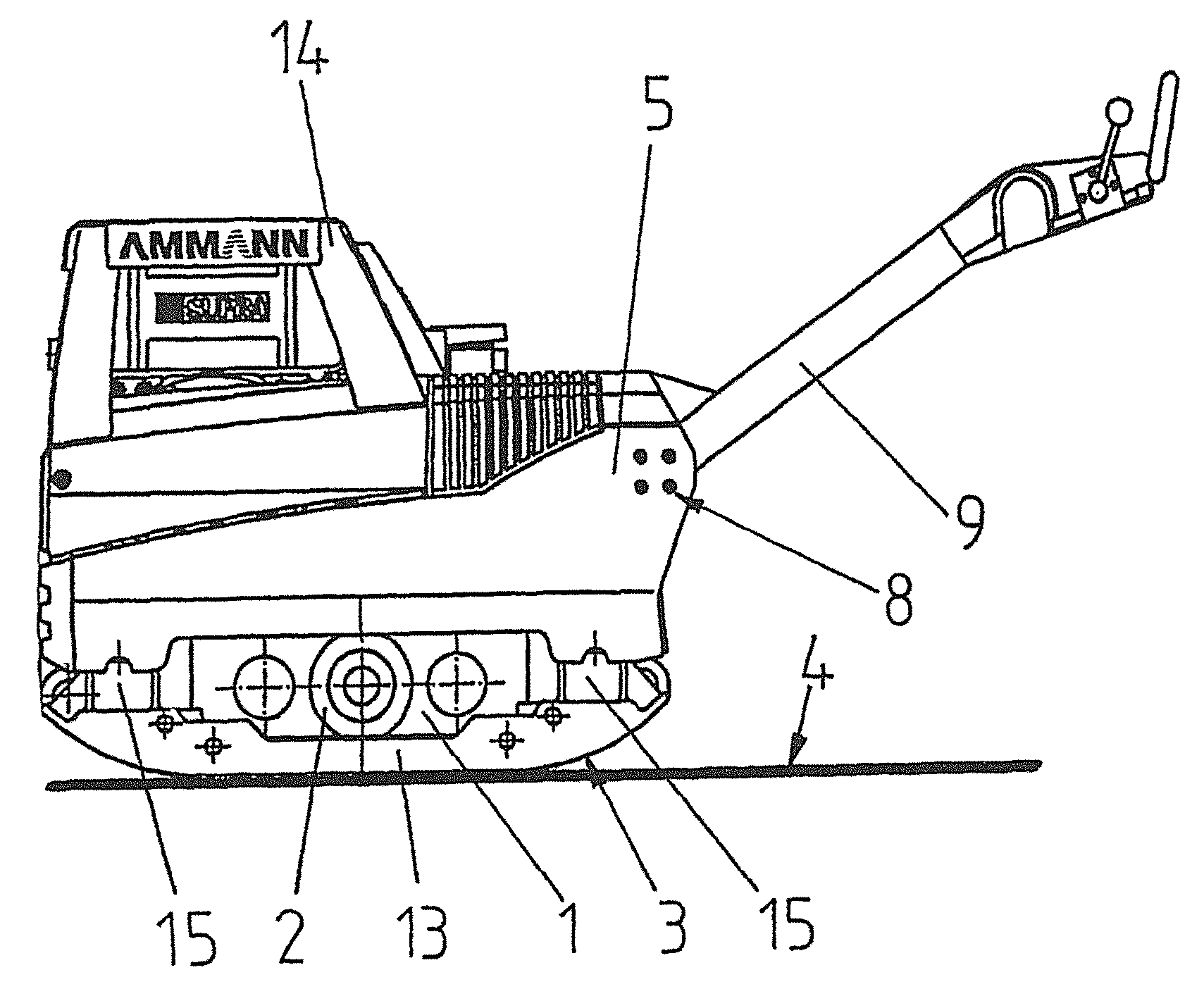
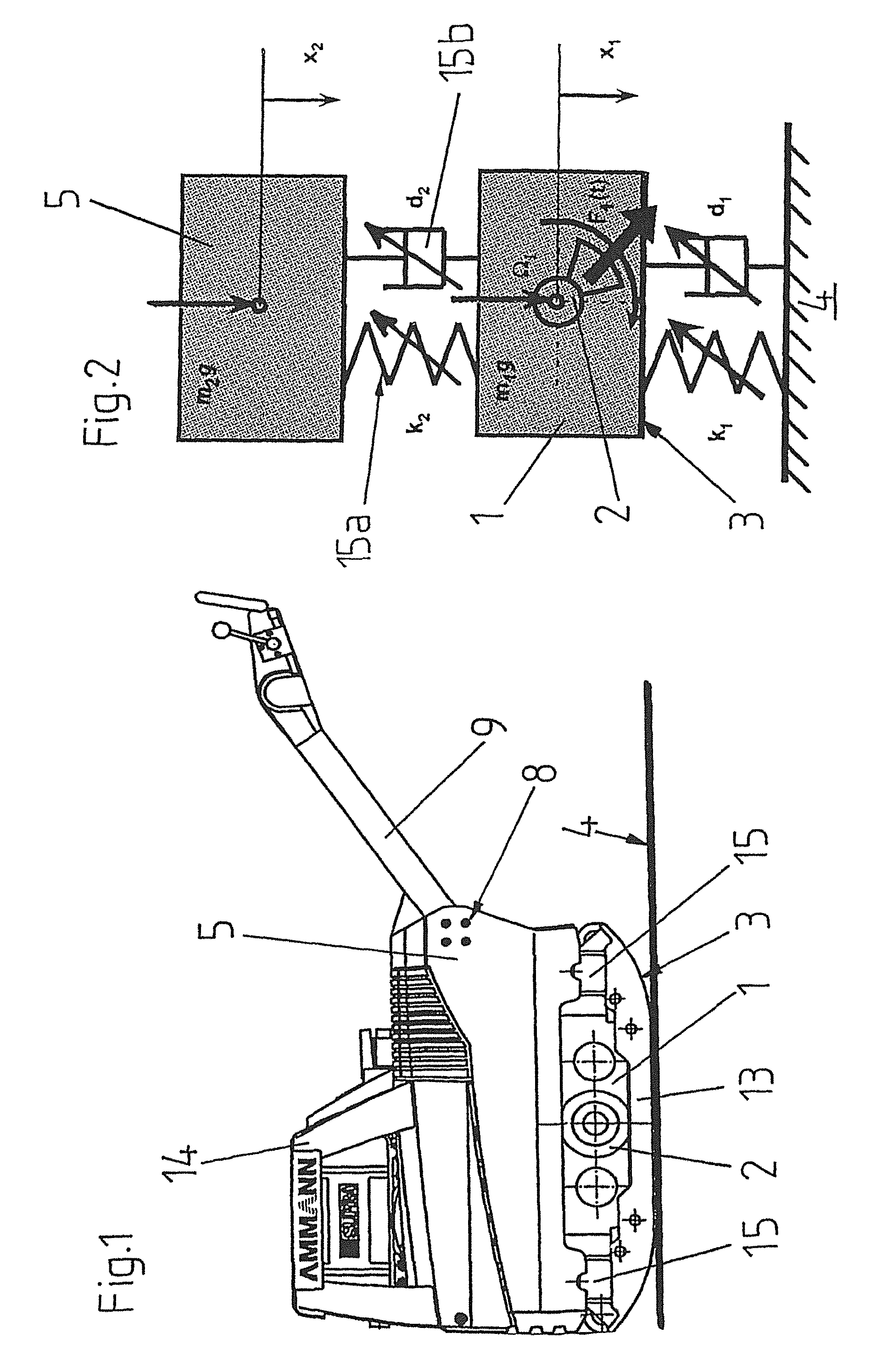
[0062]FIG. 6 shows a soil compacting device formed as a compacter in side view and FIG. 7 schematically the oscillation model of the system capable of oscillations of this compacter.

[0063]As can be seen, the compacter has a front part 19 and a rear part 20, which are connected to one another by a knee joint 21.

[0064]The front part 19 of the compacter consists substantially of a roller body 23 and a chassis frame 25.

[0065]The roller body 23 comprises a drum 11 which has the contact surface 3 for the introduction of the generated pulsing compressive force into the soil 4 to be compacted, and an unbalance exciter 2 with a hydraulic motor formed as circular vibrator, which generates an exciter force which is intermittent with respect to its direction of action and which is introduced into the drum 11.

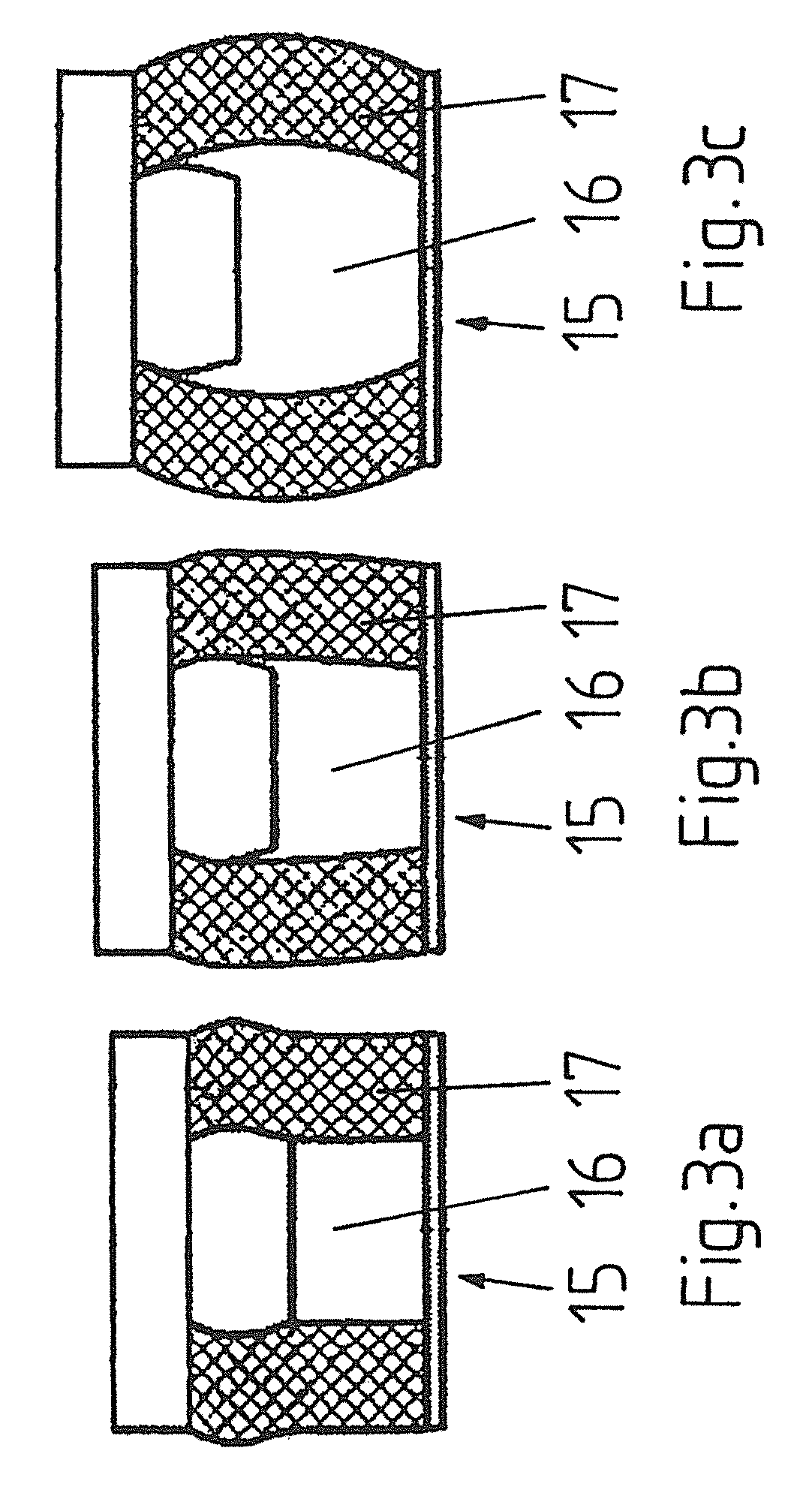
[0066]The chassis frame 25 is supported in gravity direction via two spring damper arrangements 22 (spring damper units according to the claims) with unchanged stiffness and damping on the ...

second embodiment

[0072]FIG. 8 shows a soil compacting device according to the invention, formed as a compacter, in side view.

[0073]This second compacter differs from the first compacter shown in FIG. 6 only by the fact that the rear part 20 of the compacter is formed by a wheel bearing which is supported entirely on four actuating wheels 10a, 10b of two axes arranged one after the other and is connected to the chassis frame 25 in such a way that it only guides and actuates the latter in horizontal direction, when operated as intended, but does not receive from it or transmit to it any forces acting in vertical direction. Here, the rear part 20 is also decoupled in terms of oscillations from the chassis frame 25 and the roller body 23 of the front part 19 of the compacter and therefore forms an idle part, as according to the claims.

third embodiment

[0074]FIG. 9 shows a soil compacting device according to the invention, formed as a compacter, in side view. This is an unmanned compacter which is operated by a radio remote control.

[0075]As can be seen, this third compacter comprises a roller body 23 (exciter part according to the claims) and a chassis frame 25 (vibration damper part according to the claims), which is supported in gravity direction at one end via two spring damper arrangements 22 (spring damper unit according to the claims) with unchanged stiffness and damping on the two end-side bearings of the roller body 23 and at the other end on two actuating wheels 10 actuated by hydraulic motors.

[0076]The roller body 23 comprises a drum 11 which has the contact surface 3 for the introduction of the generated pulsing compressive force into the soil 4 to be compacted, and an unbalance exciter 2 formed as a circular vibrator with a hydraulic motor, which generates a force which is intermittent with respect to its direction of ...


PUM


Abstract

The invention relates to a soil compacting device having an exciter part (1), which has an unbalance exciter (2) for producing an intermittent exciter force and a contact surface (3) for transmitting a force component of the exciter force directed perpendicularly to the contact surface (3) to the soil surface (4) to be compacted as a pulsing compressive force. The device also has a vibration damper part (5), which is connected to the exciter part (1) by means of a spring-damper unit (15). The spring stiffness of the spring-damper unit (15), the damping of the spring damper unit (15), the spring pre-load of the spring-damper unit (15), the mass of the vibration damper part (5), the mass moment of inertia of the vibration damper part (5), the mass of the exciter part (1), and / or the mass moment of inertia of the exciter part (1) can be varied during operation.

Description

CROSS REFERENCE TO RELATED APPLICATIONS[0001]This application claims the priority of PCT Application No. PCT / CH2010 / 000104, filed on Apr. 16, 2010, the disclosures of which are incorporated herein by reference in their entirety.TECHNICAL FIELD[0002]The invention relates to an arrangement for providing a pulsing compressive force, a soil compacting device comprising such an arrangement, a method for operating such an arrangement or such a soil compacting device as well as the use of such an arrangement for compacting soil.BACKGROUND OF THE INVENTION[0003]Compacting devices which operate according to the so-called damper principle are used particularly in the field of compacting soil. An even plate or a roller body (drum), which forms the soil contact surface, is excited to oscillations by means of an unbalance exciter. The plate or the roller body is connected via a spring damper system to a damper mass arranged above it, which is also excited to oscillations via the spring damper sy...

Claims


Application Information

Patent Timeline
Patent Type & Authority Patents(United States)
IPC IPC(8): E01C19/26E01C19/22
CPCE02D3/074
Inventor ANDEREGG, ROLANDGERHARD, MARTINKAUFMANN, KUNOVON FELTEN, DOMINIK ANTON
Owner AMMANN SCHWEIZ
Why Eureka
Try Eureka