
Whirlpool skimmer

Inactive Publication Date: 2014-05-20
IACOVACCI JOSEPH
View PDF9 Cites 9 Cited by
  • Summary
  • Abstract
  • Description
  • Claims
  • Application Information

AI Technical Summary

Benefits of technology

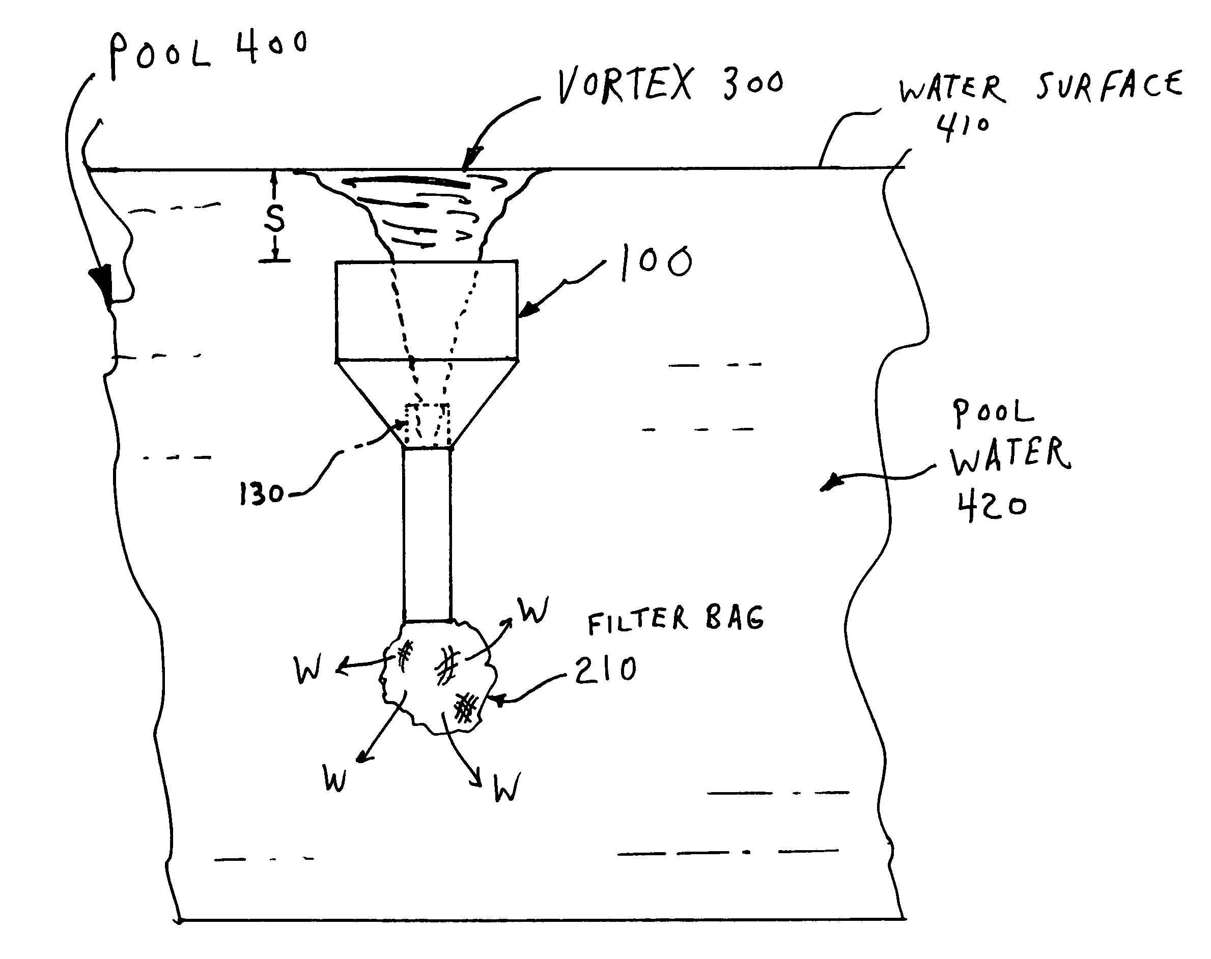
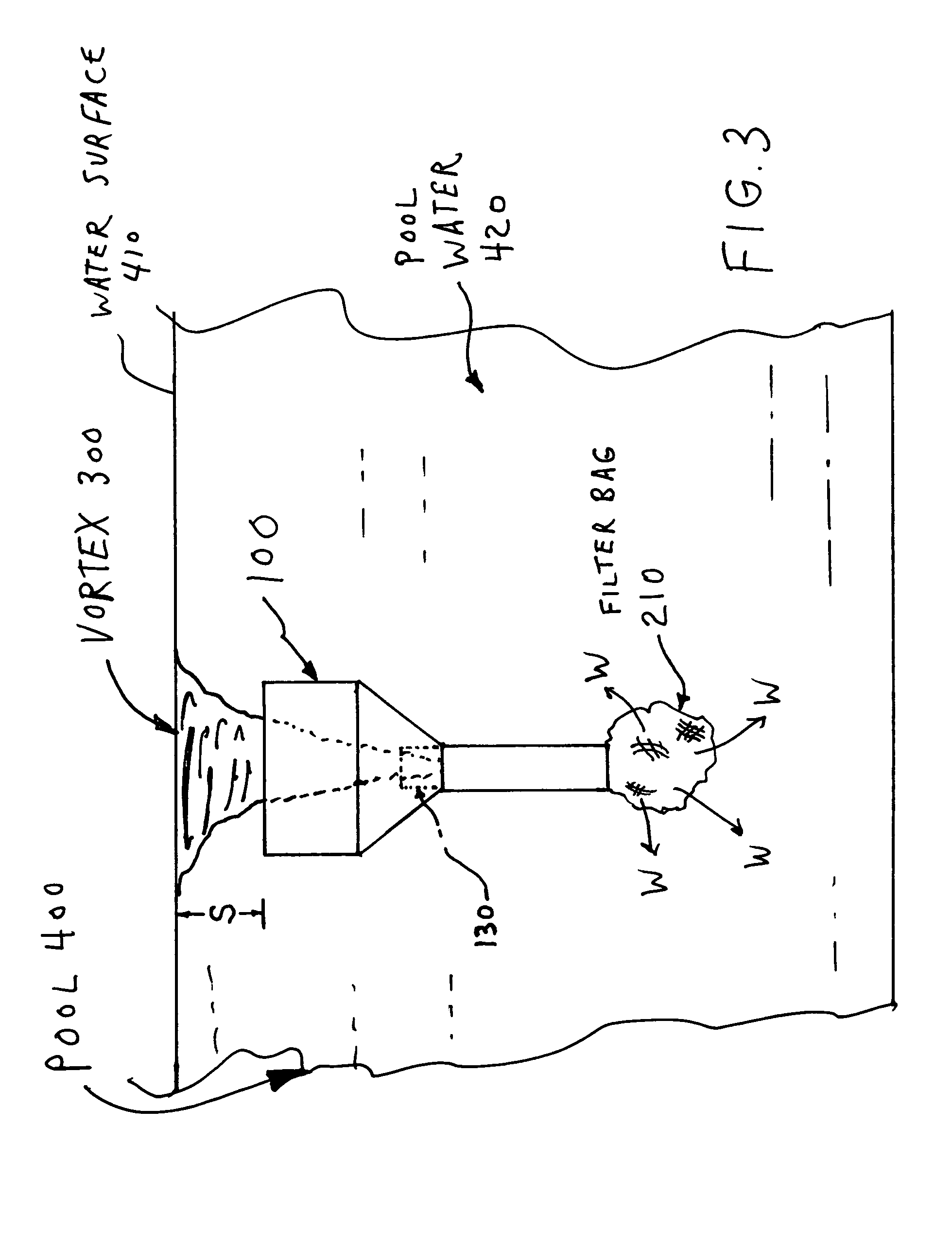
The device of the present invention creates a rotational flow pattern that causes coaxial rotational flow patterns. This results in a rising outer rotational flow that helps to direct the force of the vortex above the topmost portion of the funnel portion to the surface of the pool. This beneficial effect is achieved when the topmost portion of the funnel portion is placed below the water surface by a distance of preferably one to four inches.

Problems solved by technology

From the foregoing, it is seen that it is a problem in the art to provide a device meeting the above requirements.

Method used


Image

  • Whirlpool skimmer
  • Whirlpool skimmer
  • Whirlpool skimmer

Examples


working embodiment

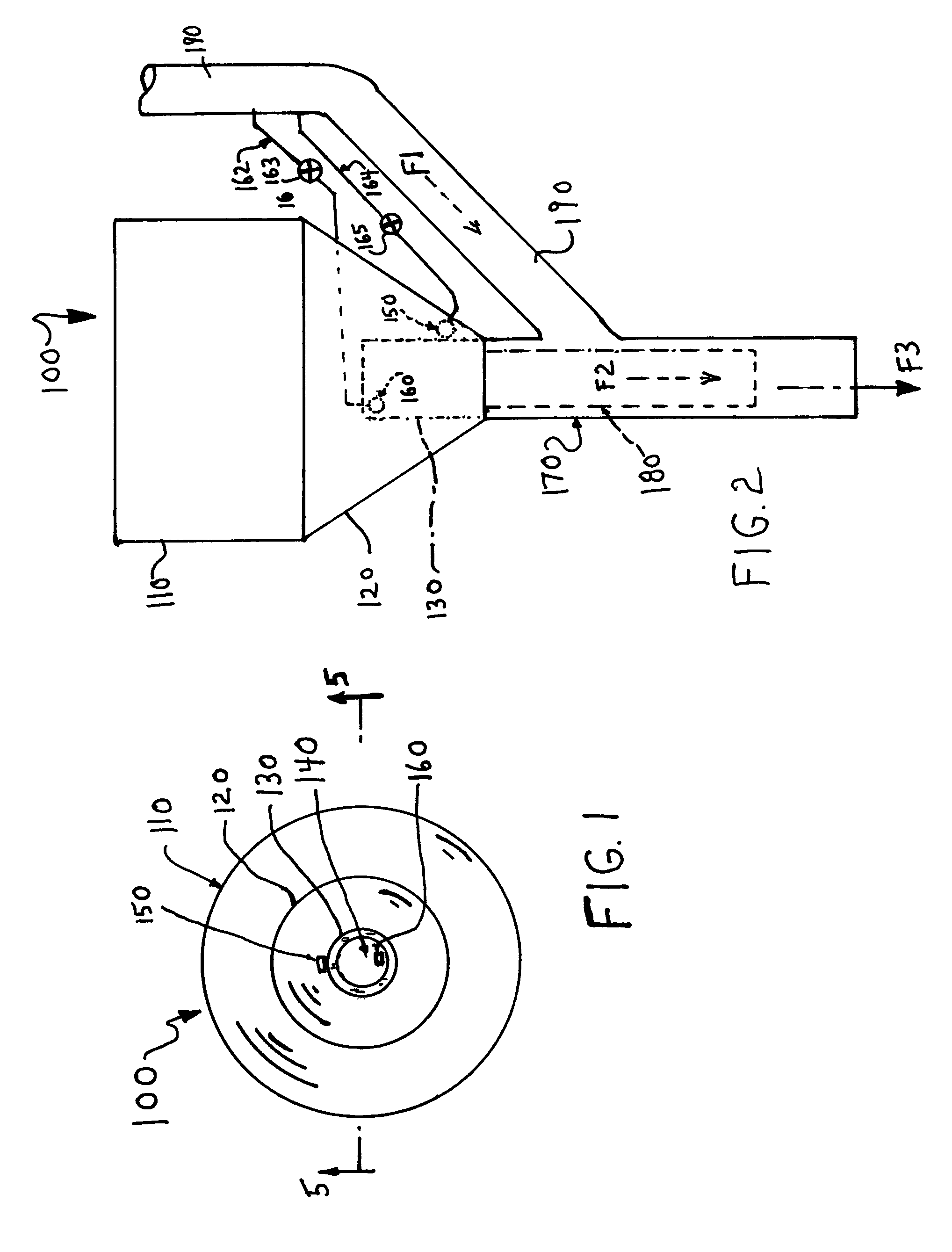
[0045]In a working embodiment, the dimensions of the parts are preferably as follows. The pipe 170 can be composed of standard PVC pipe with a 2 inch diameter, and the pipe 180 a similar pipe but with a 1.25 inch diameter. The pipe 190 is preferably similar to the pipe 170, or can be larger or smaller, for example 1.5 inches, as long as it can supply a sufficient water flow. The diameter of the inner cup-shaped portion 130 is three inches in the working embodiment, while the diameter of the funnel portion 110 is nine inches in the working embodiment. The conduits 162 and 164 in the working embodiment are formed by flexible plastic tubing having a one-quarter inch diameter. The length of the funnel portion 110 is ten inches in the working embodiment, and the inner, tapering funnel-shaped portion 120 begins to taper at a point six inches below the uppermost edge of the funnel portion 110 as viewed in FIG. 2. The depth (length) of the inner cup-shaped portion 130 is four inches.

[0046]T...


PUM

PropertyMeasurementUnit
distanceaaaaaaaaaa
distanceaaaaaaaaaa
diameteraaaaaaaaaa

Abstract

A whirlpool skimming device removes surface debris from a pool by creating a whirlpool having an upper bound at the surface of the pool. The uppermost portion of the whirlpool is free standing and is not bounded by the device. The device includes an outer cup-shaped portion and an inner cup-shaped portion coaxially disposed therein. An opening is disposed in the bottom of the inner cup-shaped portion which communicates with a source of suction which is preferably a Venturi tube feeding the outlet water to a filter bag. There is a first nozzle supplying water at an upper, inner edge of the inner cup-shaped portion at a slightly downward angle in a first direction, and there is a second nozzle supplying water at a lower, outer edge of the inner cup-shaped portion and mounted on an opposite side of the inner cup-shaped portion. The device causes coaxial rotational flow patterns relative to the inner cup-shaped portion, in which the outer rotational flow takes an upwardly spiral path outside the inner cup-shaped portion, and the inner rotational flow takes a downwardly spiral path inside the inner cup-shaped portion of the device.

Description

FIELD OF THE INVENTION[0001]The present invention relates to a device for skimming liquid and debris from the surface of a pool.BACKGROUND OF THE INVENTION[0002]Pool cleaning devices are known in the prior art. For example, a skimmer and filter bag are shown in U.S. Pat. No. 5,919,359.[0003]A pool cleaning system with multiple cleaning heads is shown in U.S. Pat. No. 6,022,481.[0004]Further, a liquid surface skimmer with filter bag is shown in U.S. Pat. No. 6,027,641.[0005]A pool skimmer with filter bag and support is shown in U.S. Pat. No. 6,086,759.[0006]A telescopic arrangement is shown in a pool skimmer in U.S. Pat. No. 7,146,658.[0007]A canister filter for a swimming pool is shown in U.S. Pat. No. 7,384,544.[0008]A pool skimmer having a spray head is shown in U.S. Pat. No. 7,455,767.[0009]A circulatory swimming pool cleaning system is shown in U.S. Pat. No. 7,862,712.[0010]There is a need in the art for an efficient, effective pool cleaning device that is capable of readily rem...

Claims


Application Information

Patent Timeline
Patent Type & Authority Patents(United States)
IPC IPC(8): E04H4/12
CPCB01D21/0087B01D21/0012E04H4/1263B01D2221/02B01D21/267B01D21/0027
Inventor IACOVACCI, JOSEPH
Owner IACOVACCI JOSEPH
Learn More